

5One common assumption we encounter is that moving from 4G LTE to 5G will automatically improve network coverage. After all, newer technology should be better… right? The reality is a bit more complicated – again and again.
For many IoT applications, coverage is determined far more by frequency than by the generation of cellular technology itself. An LTE device operating on low-band can often outperform a 5G device using mid-band when it comes to indoor penetration and reach into challenging environments such as basements and utility cabinets.
Part of the early promise of 5G was that technologies such as Dynamic Spectrum Sharing (DSS) would allow operators to introduce 5G while leveraging the coverage footprint already established by LTE. While DSS certainly accelerated early deployments, many operators are now evolving their strategies as networks mature, balancing capacity, efficiency, and spectrum utilization to meet growing demand (https://www.lightreading.com/5g/the-quiet-sunset-of-5g-dynamic-spectrum-sharing).

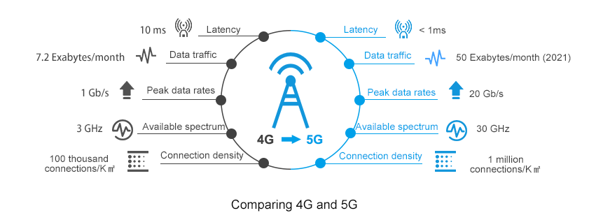
Then there’s another point: 5G Standalone (SA) vs Non-Standalone (NSA). Most of today’s 5G deployments are still NSA, meaning they continue to rely on the existing LTE core network for signalling and control. True 5G SA deployments offer the full promise of 5G with network slicing and super low latency being key factors, but they remain relatively uncommon. Or, to put it another way: 5G Standalone deployments are quite (stand)alonely!
You also have the “LPWA is 5G” proponents but we’re talking real 5G here. So what’s the takeaway? The “best” cellular technology isn’t necessarily the newest one; the right choice depends on what you’re trying to achieve.

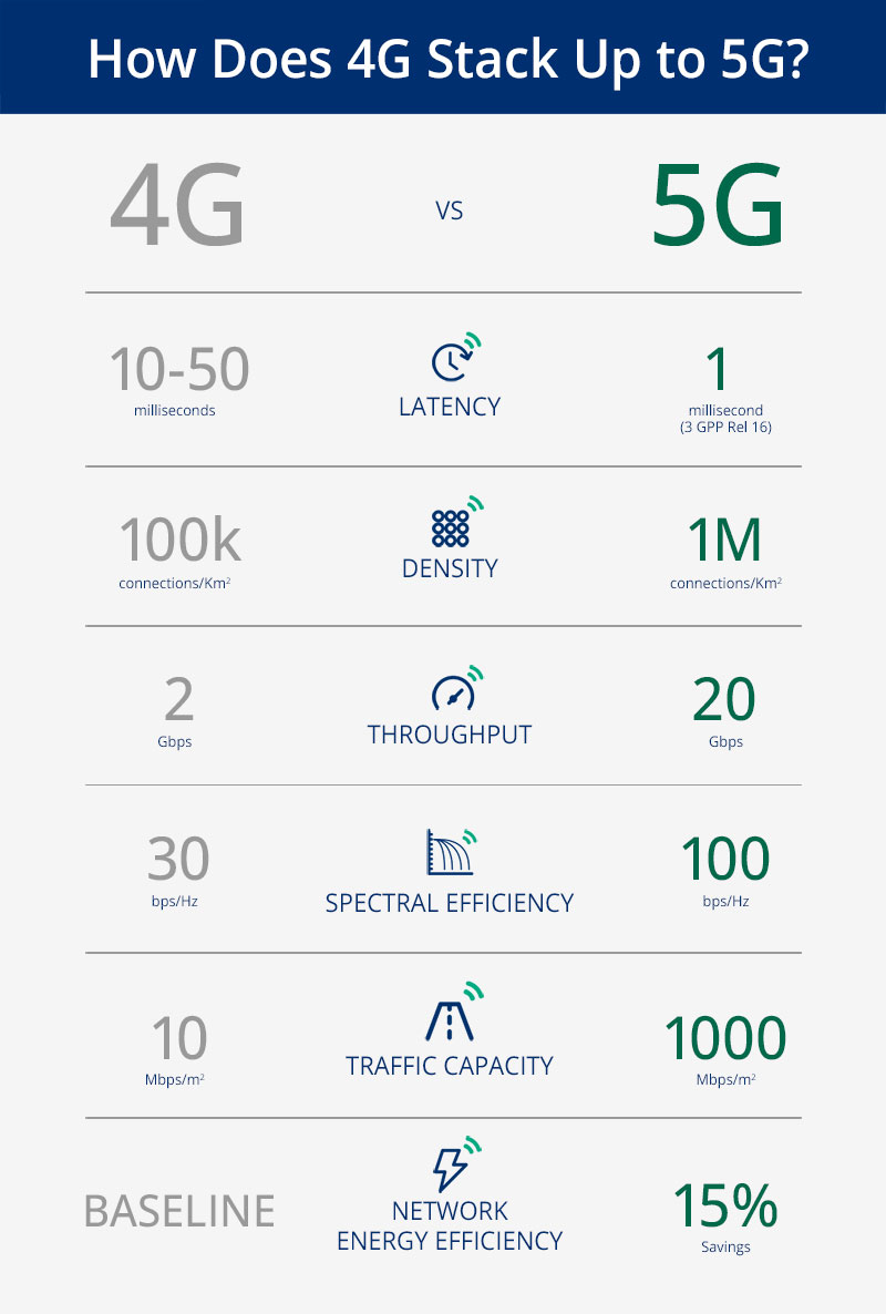
If your application requires high throughput, low latency, or is designed with future 5G capabilities in mind, then 5G may well be the obvious choice for you. On the other hand, if your priorities are coverage in difficult environments, low power consumption and/or cost control, LTE technologies still make a very compelling case. The good news? We really love this stuff.
4G Vs. 5G Key Technology Differences
Choosing the right cellular technology isn’t always straightforward, but that’s where we can help. Whether you’re evaluating LPWA, LTE, or NR, we’d be happy to discuss your application, and help you navigate the intricacies of module selection to find the best fit for your project.
In this article, I will address and review the Key technology differences between 4G and 5G; reading this topic is crucial, especially if you have a good background in 4G and have just started your 5G Career.
This article will cover the differences between 4G & 5G for the following


RAN Structure: 4G, 5G NSA & 5G SA
From the Radio Access Network side, The overall structure looks very similar, for example;
- X2 interface connecting different 4G Nodes was replaced by the Xn interface
- S1 interface connecting BTS Side to the Core network replaced by Ng interface
- MME replaced by AMF and SGW replaced by UPF
From a superficial view, it is a matter of naming change; however, there are subtle changes implemented that leads to huge improvement; we will be addressing one of the points which can lead to improving latency in 5G SA.


One of the main differences provided in 5G SA Architecture is that the User plane and Control function has separated; see below comments and the 4G & 5G Full Architecture for more details.
- An important Characteristic of the 5G System is separating the user plane and control plane functions, which differs from the original 4G System architecture in the following:
In 4G: P-GW provides both control plane and user plane functions(IP Address allocation & Packet Forwarding)
In 5G: SMF Provides IP Allocation, and UPF provides packet forwarding
2. User and Control plane separation allows independent scaling of the two functions
Operators can add more user plane capabilities without having to add more control plane
Minimize latency by distributing User plane and keeping it geographically close to the AN
Packet Gateway provides both User plane and Control Plane function in 4G


While in 5G, Only UPF provides User plane function.


Quality of Service: 4G & 5G
For the QoS Part, there is an essential change in the way of how the QoS is being allocated.
In 4G, EPS Bearer is responsible for providing E2E User Plane connectivity between the UE and Access Point Name “APN” within the Packet Gateway
*APN defines the interface to the external data network
The point here is that EPS Bearer has a one-to-one mapping to the QoS, This means that the User needs to establish a new EPS bearer every time there is a new QCI assignment, Only One QoS(Example QCI 9 can be assigned to one DRB) with no flexibility.


In 5G, PDU Sessions is responsible for providing E2E User Plane connectivity between the UE and Data Network Name “DNN” within the User Plane Function ( UPF)
*DNN defines the interface to the external data network
However, Unlike 4G EPS Bearer, PDU Session supports one or more QoS Flows, Which means that QoS Flow to radio bearer mapping is not necessarily one-to-one mapping and multiple QoS can be mapped to the same Radio Bearer.


Note: QoS Flows belonging to different PDU Sessions are mapped onto different DRBs.
Radio Protocol Stack: 4G & 5G
SDAP Primary Task:
Service Data Application Protocol (SDAP) is responsible for mapping QoS bearers to radio bearers according to their quality-of-service requirements. This protocol layer is not present in LTE but introduced in NR when connecting to the 5G core network due to the new quality-of-service handling
The new SDAP (Service Data Adaptation Protocol) primary function maps each QoS Flow onto a specific Data Radio Bearer
•Multiple QoS Flows can be mapped onto a single DRB or,
•Single QoS Flow can be mapped onto a single DRB.


Overall Technology Comparison


4G Vs. 5G Bandwidth
4G Supports a maximum up to 20Mhz BW, While 5G is up to 400Mhz
5G offers less Guard Band(2~5) and Higher Spectrum Utilization(Utilizing up to 95% of the Channel BW, While 4G Utilize 90%)
Up to 20x Higher Bandwidth and New Spectrum Definition. (ex. mmwave)
NR Offers Less Guard-band and Higher spectrum utilization


Frame Structure Comparison: 4G & 5G
The following summarized the main differences between 4G & 5G Frame Structure
- Frame and Subframe duration remained the Same for 5G
- Number of Symbols in a slot is now fixed to 14 in 5G (4G is fixed to 7)
- 5G has a flexible numerology, which allows different configurations as the Slot Duration relies on SCS(Sduration = 1 /SCS)
- 5G is now using a Slot as a scheduling Unit instead of Sub-frame compared to 4G
- NR RB Resource Grid is double 4G(14 vs. 7 OFDM symbols in one RB )


Physical Channel & Signals Comparison : 4G & 5G
The below table summarizes the main differences in Physical Channel and Signals


Downlink Comparison: Physical Downlink Control Channel(PDCCH)
- In LTE, PDCCH control channels are always distributed across the entire system bandwidth.
- NR PDCCHs are designed to transmit in a configurable control resource set (Called CORESET).


Uplink Comparison: Physical Uplink Control Channel(PUCCH)
In 4G, PUCCH is transmitted in one or more Physical Resource Blocks (PRB) at the edges of the system bandwidth and is only supporting Long-Format(duration 1 ms)


While 5G supports both Long and short format, Where short format provides the following:
- 1~2 Symbols over the complete
- Provides Better Latency


PBCH & Synchronization Signals: 4G & 5G
There are 2 main changes in PBCH and SS compared to 4G:
PBCH and SS are now being combined into SSB
SSB Frequency domain location is flexible and can be configured at different locations based on the network requirements(4G PBCH & SS are fixed at the center of Channel BW)


Broadcast Channel Comparison: 4G & 5G
4G Provide Wide Beam coverage, while 5G provides narrow beam coverage for broadcast channels, which can improve the Coverage and Quality


Reference Signal Overhead comparison: 4G & 5G
5G Overhead is almost half 4G, and the mean reason behind that 5G has no Cell Specific Reference Signal as 4G
As you know that CRS was all the time transmitted “Always on” over the entire BW and consume a large number of resource elements within the Resource block
While 5G uses DMRS for channel demodulation instead of CRS.
PDSCH DMRS offers much less overhead compared to CRS due to the following:
DMRS is transmitted within the set of RBs allocated to PDSCH. i.e, if a UE is allocated 10RBs for PDSCH, then both PDSCH and DMRS will be transmitted across those BW
DMRS Configuration type 1 uses 6 RS within one or two symbols, which add around 3.6% up to 7% overhead to 5G, while 4G offers from 9% to 17% overhead. Please see the below picture for more details and refer to the below-attached video for more information.


Key differences in Link Budgets: 4G & 5G
4G & 5G almost have the same Link Budget Basic Methodology
Link Budget is counting all of the gains and losses from the TX through the medium(Free Space, Cables, etc.) to the receiver
Simple Link Budget Equation:
•Received Power(dBm) = TX Power(dBm) + Gains – Losses


Main consideration:


Materials uploaded to below blog