Technical reference · 12 September 2026
| Specification | Configuration |
|---|---|
| Radio / platform | Wi-Fi 7 | three two-stream radio cells |
| Theoretical PHY reference | 573.6 / 2882 / 5765 Mb/s by band |
| Host / processor | IPQ9574; quad-core Cortex-A73 at 2.2 GHz |
| Channel / network configuration | 10GbE RJ45 + 10G SFP + 2 x 1GbE |
| RF / power | 6 x MMCX; 2 x M.2; revision-matched power input |
| Mechanical / environment | 161 x 110 x 16 mm |
| Parameter | Pulse B7-02 |
|---|---|
| Processor | IPQ9574; four Cortex-A73 cores at 2.2 GHz |
| Memory interface | DDR4, 32-bit interface; delivered memory option as ordered |
| Copper and optical network | One 10GbE RJ45, one 10G SFP and two 1GbE ports |
| RF allocation | Three two-stream radio groups; six MMCX connectors |
| Engineering interfaces | UART and SGMII; two M.2 positions with purpose matched to the assembly |
| Power integration | Match DC/PoE input and M.2 slot wiring to the delivered board revision |
| Mechanical envelope | 161 x 110 x 16 mm |
| Environmental design | -40 to +70 C operating; -40 to +90 C storage |
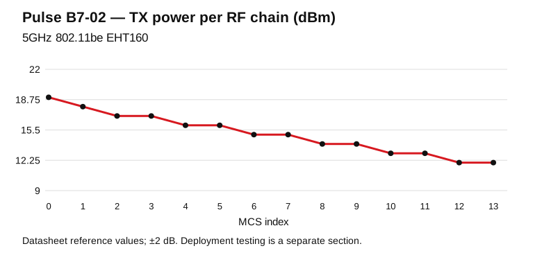
Model-specific datasheet reference points for RF design. TX is conducted power per RF chain; RX is input sensitivity. Configure channel, output power and antenna gain for the operating country.
| MCS | TX / chain (dBm) | RX sensitivity (dBm) |
|---|---|---|
| MCS0 | 19.0 | -88.0 |
| MCS1 | 18.0 | -86.0 |
| MCS2 | 17.0 | -83.0 |
| MCS3 | 17.0 | -80.0 |
| MCS4 | 16.0 | -78.0 |
| MCS5 | 16.0 | -76.0 |
| MCS6 | 15.0 | -74.0 |
| MCS7 | 15.0 | -71.0 |
| MCS8 | 14.0 | -68.0 |
| MCS9 | 14.0 | -66.0 |
| MCS10 | 13.0 | -63.0 |
| MCS11 | 13.0 | -60.0 |
| MCS12 | 12.0 | -56.0 |
| MCS13 | 12.0 | -53.0 |
Reference tolerance: ±2 dB.
| MCS | TX / chain (dBm) | RX sensitivity (dBm) |
|---|---|---|
| MCS0 | 19.0 | -82.0 |
| MCS1 | 18.0 | -79.0 |
| MCS2 | 17.0 | -76.0 |
| MCS3 | 17.0 | -73.0 |
| MCS4 | 16.0 | -70.0 |
| MCS5 | 16.0 | -67.0 |
| MCS6 | 15.0 | -63.0 |
| MCS7 | 15.0 | -61.0 |
| MCS8 | 14.0 | -58.0 |
| MCS9 | 14.0 | -56.0 |
| MCS10 | 13.0 | -53.0 |
| MCS11 | 13.0 | -51.0 |
| MCS12 | 12.0 | -49.0 |
| MCS13 | 12.0 | -47.0 |
Reference tolerance: ±2 dB.
Use the complete board-specific system image for Pulse B7-02, including its bootloader, device tree, Ethernet switch/PHY configuration and radio calibration. Preserve the existing flash partition map and calibration partitions before an upgrade. Match the recovery procedure to the board revision and serial header.
| Integration item | Model-specific preparation |
|---|---|
| Platform | IPQ9574; quad-core Cortex-A73 at 2.2 GHz |
| Network verification | 10GbE RJ45 + 10G SFP + 2 x 1GbE |
| Image identity | Record release/build, board revision, image checksum and the partition layout. |
| OpenWrt / QSDK workflow | Select a board-targeted build approved for the delivered assembly; radio-driver support is only one part of the complete image. |
| First boot | Capture the UART boot log; verify memory, flash, Ethernet link negotiation and each installed radio. |
Use the following commissioning procedure for Pulse B7-02. This is a test method, separate from the theoretical PHY specifications and datasheet RF references above.
| Step | Record and verify |
|---|---|
| Baseline | Model/revision, firmware build, host CPU, uplink speed, channel width, country profile, antennas and client spatial streams. |
| Link verification | Capture negotiated PHY, RSSI per chain and noise/retry statistics before sustained traffic. |
| Wired reference | Measure the wired path first; select a server link appropriate to 573.6 / 2882 / 5765 Mb/s by band. |
| Traffic test | Run TCP in each direction, then concurrent clients; record duration, CPU load, temperatures and retransmissions. |
| Site acceptance | Repeat at the intended mounting positions; save results with the exact configuration for comparison. |
524WiFi™ engineering support · Tomorrow Systems®