Technical reference · 12 September 2026
| Specification | Configuration |
|---|---|
| Radio / platform | Wi-Fi 7 | 2x2 | 2.4 / 5 / 6 GHz |
| Theoretical PHY reference | 688 / 2882 / 5765 Mb/s by band |
| Host / processor | QCN9274 industrial variant; Mini PCIe / PCIe 3.0 |
| Channel / network configuration | 40 / 160 / 320 MHz maximum by band |
| RF / power | 2 x U.FL; 3.3 V; 9 W maximum |
| Mechanical / environment | 30 x 50.8 x 12.5 mm; industrial -40 to +85 C |
| Parameter | Pulse P7-09 |
|---|---|
| RF tuning ranges | 2412-2482 MHz; 5150-5825 MHz; 5945-7125 MHz |
| RF allocation | Two U.FL connectors; select the required operating-band profile |
| Power input | 3.3 V; 9 W maximum |
| Mechanical envelope | 30 x 50.8 x 12.5 mm |
| Temperature selection | Commercial: -20 to +70 C; industrial: -40 to +85 C; choose the ordered grade |
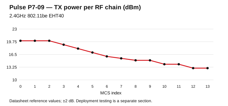
Model-specific datasheet reference points for RF design. TX is conducted power per RF chain; RX is input sensitivity. Configure channel, output power and antenna gain for the operating country.
| MCS | TX / chain (dBm) | RX sensitivity (dBm) |
|---|---|---|
| MCS0 | 20.0 | -88.0 |
| MCS1 | 20.0 | -87.0 |
| MCS2 | 20.0 | -85.0 |
| MCS3 | 19.0 | -85.0 |
| MCS4 | 18.0 | -82.0 |
| MCS5 | 17.0 | -79.0 |
| MCS6 | 16.0 | -76.0 |
| MCS7 | 15.5 | -73.0 |
| MCS8 | 15.0 | -70.0 |
| MCS9 | 15.0 | -65.0 |
| MCS10 | 14.0 | -61.0 |
| MCS11 | 14.0 | -59.0 |
| MCS12 | 13.0 | -54.0 |
| MCS13 | 13.0 | -53.0 |
Reference tolerance: ±2 dB.
| MCS | TX / chain (dBm) | RX sensitivity (dBm) |
|---|---|---|
| MCS0 | 19.0 | -84.0 |
| MCS1 | 18.0 | -82.0 |
| MCS2 | 17.0 | -80.0 |
| MCS3 | 17.0 | -78.0 |
| MCS4 | 16.0 | -75.0 |
| MCS5 | 16.0 | -72.0 |
| MCS6 | 15.0 | -70.0 |
| MCS7 | 15.0 | -68.0 |
| MCS8 | 14.0 | -65.0 |
| MCS9 | 14.0 | -63.0 |
| MCS10 | 13.0 | -60.0 |
| MCS11 | 13.0 | -58.0 |
| MCS12 | 12.0 | -53.0 |
| MCS13 | 12.0 | -50.0 |
Reference tolerance: ±2 dB.
| MCS | TX / chain (dBm) | RX sensitivity (dBm) |
|---|---|---|
| MCS0 | 19.0 | -82.0 |
| MCS1 | 18.0 | -79.0 |
| MCS2 | 17.0 | -76.0 |
| MCS3 | 17.0 | -73.0 |
| MCS4 | 16.0 | -70.0 |
| MCS5 | 16.0 | -67.0 |
| MCS6 | 15.0 | -63.0 |
| MCS7 | 15.0 | -61.0 |
| MCS8 | 14.0 | -58.0 |
| MCS9 | 14.0 | -56.0 |
| MCS10 | 13.0 | -53.0 |
| MCS11 | 13.0 | -51.0 |
| MCS12 | 12.0 | -49.0 |
| MCS13 | 12.0 | -47.0 |
Reference tolerance: ±2 dB.
Pulse P7-09 uses the ath12k driver family for Linux integration. Prepare the PCIe host, driver, device firmware and calibration as one matched software set. For an OpenWrt host, choose packages built for that host release and kernel ABI, then verify the detected device and radio profiles.
| Integration item | Configuration |
|---|---|
| Radio platform | QCN9274 industrial variant; Mini PCIe / PCIe 3.0 |
| Driver family | ath12k |
| Firmware lookup family | /lib/firmware/ath12k/QCN9274/hw2.0/ — confirm the path requested in the device boot log |
| Board data | Retain the unit calibration and revision-specific board data; match the PCI/subsystem and board identity. |
| Radio profile | Wi-Fi 7 | 2x2 | 2.4 / 5 / 6 GHz; 40 / 160 / 320 MHz maximum by band |
| Read-only first checks | lspci -nnk; dmesg; iw phy; iw dev; iw reg get |
Use the following commissioning procedure for Pulse P7-09. This is a test method, separate from the theoretical PHY specifications and datasheet RF references above.
| Step | Record and verify |
|---|---|
| Baseline | Model/revision, firmware build, host CPU, uplink speed, channel width, country profile, antennas and client spatial streams. |
| Link verification | Capture negotiated PHY, RSSI per chain and noise/retry statistics before sustained traffic. |
| Wired reference | Measure the wired path first; select a server link appropriate to 688 / 2882 / 5765 Mb/s by band. |
| Traffic test | Run TCP in each direction, then concurrent clients; record duration, CPU load, temperatures and retransmissions. |
| Site acceptance | Repeat at the intended mounting positions; save results with the exact configuration for comparison. |
524WiFi™ engineering support · Tomorrow Systems®