
Description

524WiFi Signal Plus™: Three matched RF paths for discreet 3×3 MIMO ceiling coverage
Engineered for receive and transmit. 524WiFi Signal Plus™ is our technical designation for an antenna whose frequency range, elements, MIMO ports, 50-ohm impedance, gain and matching are specified as one complete RF system. A passive antenna uses the same reciprocal RF path in both directions: it receives signals and radiates the transmitter power supplied by the connected radio.
Three integrated antenna feeds distribute service through a 360° horizontal pattern, with 3 dBi gain at 2.4 GHz and 4 dBi across 4.9-7.125 GHz. VSWR remains below 2. This gives installers a specification-led choice instead of a vague one-size-fits-all accessory. It is not an active amplifier and does not create additional transmitter power; the advantage comes from selecting the correct pattern, gain, ports, polarization and connectors for the real installation.
- 3×3 MIMO with three RF paths
- 3 / 4 dBi documented gain
- VSWR <2
- 360° horizontal ceiling coverage
Documented gain by frequency range
Bar lengths are normalized within this product for quick comparison; the printed dBi values are authoritative. End-to-end results also depend on radio power, cable loss, placement, alignment, interference and local network conditions.
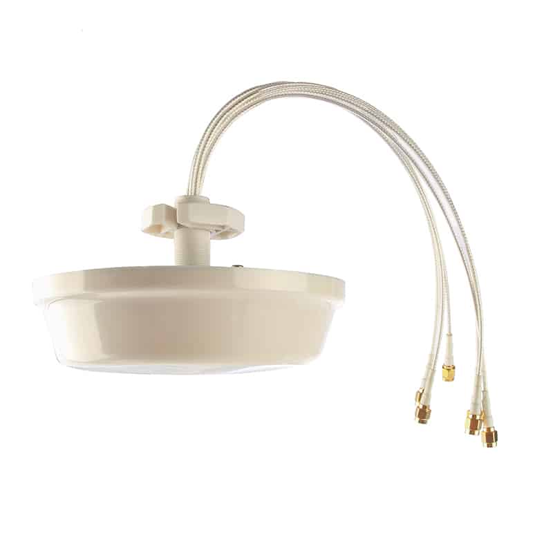
524WiFi™ Ceiling Wi-Fi 6E Omnidirectional Antenna, 3×3 MIMO, 2.4/5/6 GHz, 3/4 dBi, 3x SMA Male
A compact three-port ceiling antenna for 3×3 MIMO indoor Wi-Fi coverage. Its omnidirectional pattern distributes service around a central ceiling position across 2.4 GHz and the extended 4.9-7.125 GHz range.
Key benefits
- 3×3 MIMO with three independent antenna feeds
- 2400-2500 MHz and 4900-7125 MHz operating bands
- 3 dBi gain at 2.4 GHz and 4 dBi at 4.9-7.125 GHz
- 360° horizontal coverage for indoor access points
- Three SMA male connectors on 30 cm white LMR100 cables
- Compact white ABS radome for ceiling mounting
Recommended applications
- Indoor access points with three external antenna ports
- Hotels, offices, retail and residential buildings
- Wi-Fi 6 and Wi-Fi 6E coverage
- Central ceiling positions requiring all-around coverage
Installation and compatibility
Connect all three SMA male leads to the matching ports of one 3×3 MIMO radio. Verify that the equipment uses standard SMA female connectors; RP-SMA is different and will not mate correctly. Avoid placing the antenna immediately beside large metal objects. Use of 6 GHz requires compatible equipment and compliance with local regulations.
Technical specifications
| Frequency range | 2400-2500 MHz; 4900-7125 MHz |
|---|---|
| Gain | 3 dBi; 4 dBi |
| MIMO / ports | 3×3 MIMO; 3 ports |
| Polarization | Vertical |
| Horizontal beamwidth | 360° |
| Vertical beamwidth | 68° at 2.4 GHz; 55° at 4.9-7.125 GHz |
| VSWR | <2 |
| Impedance | 50 ohms |
| Maximum input power | 50 W |
| Lightning protection | DC ground |
| Connectors and cable | 3x SMA male; 30 cm white LMR100 |
| Dimensions / weight | Ø120 x 35 mm; 0.2 kg |
| Mounting | Ceiling mount |
| Radome | ABS, white |
| Operating temperature | -40°C to +65°C |
Package contents
- 524WiFi™ ceiling antenna
- Three integrated 30 cm white LMR100 leads with SMA male connectors
- Ceiling-mount hardware
524WiFi™ model: 524WIFI-TCC-2472-4CV
Actual wireless performance depends on the connected equipment, cable losses, installation, radio environment and applicable local regulations.
Why a ceiling omnidirectional antenna is the right tool for indoor Wi-Fi
A ceiling antenna places the RF source above the occupied space, clear of desks, equipment cabinets and much of the furniture that can absorb or scatter a wireless signal. The 524WIFI-TCC-2472-4CV uses a full 360° horizontal radiation pattern, so it can serve clients around the mounting point instead of concentrating energy into one narrow direction. That makes it a natural choice for a centrally positioned access point in an office, hotel, classroom, retail floor, clinic, meeting area or other indoor zone.
This is not a decorative “puck” with an unknown element inside. The antenna is specified across 2400–2500 MHz and 4900–7125 MHz, covering the 2.4 GHz band plus the 5 GHz and 6 GHz ranges used by compatible Wi-Fi equipment. Documented gain is 3 dBi at 2.4 GHz and 4 dBi from 4.9 to 7.125 GHz, with VSWR below 2. Those values give a system designer real numbers for link-budget and placement decisions.
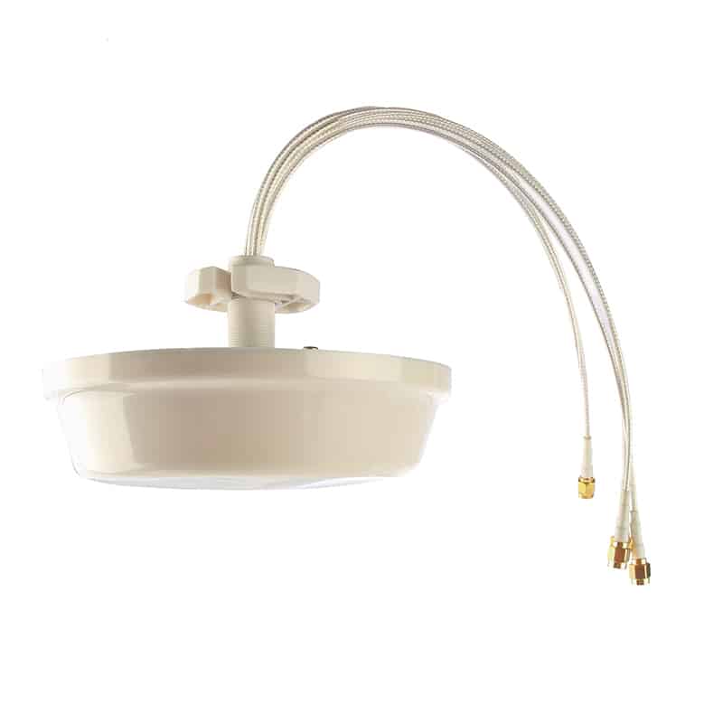
Three matched RF paths in one clean ceiling radome
Three integrated feeds match access points and radio platforms designed for three external antenna paths. The compact Ø120 × 35 mm housing and 0.2 kg weight make it discreet in offices, shops, hospitality spaces and managed residential deployments while preserving one consistent coverage centre.
The short integrated 30 cm white LMR100 leads keep the transition from antenna to radio compact. Each lead terminates in SMA male, so the connected access point, radio module or approved extension assembly must present the correct SMA female interface. Standard SMA and RP-SMA are mechanically similar but electrically different; always verify the centre contact before installation.
Coverage behaviour: 360° around the antenna, shaped vertically for the room below
“Omnidirectional” describes the horizontal plane. Viewed from above, the pattern is designed to radiate around the full circle. In the vertical plane the documented beam width is 68° at 2.4 GHz and 55° at 4.9–7.125 GHz. The narrower high-band vertical pattern is normal antenna behaviour: as frequency and gain change, the usable energy is shaped differently. In practice, mounting height, ceiling construction and the position of clients determine how that pattern fills the occupied zone.
68° vertical beam at 2.4 GHz · 55° vertical beam at 4.9–7.125 GHz
For predictable coverage, mount the radome close to the centre of the intended service area and below major metal obstructions. A steel beam, HVAC duct, cable tray or foil-backed insulation immediately beside the antenna can distort the pattern. If the room is long and narrow, divided by dense walls or spread across several floors, one centrally mounted omni antenna may not be the correct architecture; several lower-power cells or a directional solution can produce cleaner roaming and frequency reuse.
What 3×3 MIMO means in a real installation
MIMO uses multiple independent RF paths so a compatible radio can work with spatial streams and multipath instead of treating every reflected signal as a problem. The 524WIFI-TCC-2472-4CV provides three antenna ports in one housing. To obtain the intended 3×3 configuration, connect every antenna lead to the corresponding RF port of equipment designed for three external antenna paths. The antenna does not create additional spatial streams by itself; the radio, chipset, firmware, channel width, client capability and RF environment determine the negotiated link.
The three-port version is a practical fit for established 3×3 access-point architectures. It keeps all three radiators at the same ceiling position and supplies three short, clearly serviceable leads. Compared with a six-port assembly, it reduces cable count and enclosure size where the radio cannot use more than three external paths.
Do not connect several leads to unrelated radios unless the entire RF design has been engineered for that arrangement. Do not transmit into an unconnected active radio port. Label the cables before closing the ceiling, keep adapters to a minimum and maintain a gentle cable bend radius. These small installation disciplines protect matching, reduce avoidable loss and make later service much easier.
Designed for both receive and transmit
A passive antenna is reciprocal: the same RF structure that collects energy from a client during reception also radiates energy supplied by the access point during transmission. 524WiFi Signal Plus™ therefore describes the complete bidirectional RF path — supported bands, gain, pattern, impedance, port count, matching and connector implementation — rather than an imaginary amplifier. There is no active booster or hidden transmitter inside the radome.
On receive, suitable placement and matching help the radio recover weaker client signals without adding active electronics at the antenna. On transmit, the antenna shapes the power delivered by the radio into its documented pattern. Legal EIRP, channel availability and permitted indoor use remain controlled by the connected equipment, its configuration and the regulations of the country where the system operates.
Best deployment scenarios
Balanced coverage around a central ceiling point for laptops and mobile clients.
A discreet white radome for guest, POS and staff wireless networks.
A direct physical match for compatible 3×3 external-antenna radios.
This model is strongest in small-to-medium indoor cells where the access point has three external ports and users surround the mounting position. It suits centrally located rooms and zones; for long corridors, outdoor areas or a remote target in one direction, choose an antenna pattern designed for that geometry.
Installation workflow for repeatable results
- Confirm the radio interface. Verify 3×3 external antenna support, 50-ohm RF ports and SMA female connectors. Confirm that the radio actually supports the required 2.4, 5 or 6 GHz channels.
- Survey the ceiling position. Choose a point with clear exposure to the occupied area. Check for metal services above the tile and for nearby objects that could shadow the antenna.
- Plan cable routing before drilling. The integrated leads are 30 cm LMR100. Decide whether the radio can be placed nearby or whether a correctly specified low-loss extension is required. Every adapter and metre of cable adds loss, especially at 5 and 6 GHz.
- Mount without loading the connectors. Secure the ceiling hardware, support the radio cables separately and leave strain relief so movement of the cable cannot pull on the SMA interfaces.
- Connect all paths consistently. Tighten RF connectors correctly; do not cross-thread or over-torque them. Keep port labelling consistent with the access-point documentation.
- Validate in both directions. Test downstream and upstream performance at representative client positions. A strong access-point signal alone does not prove that low-power phones, sensors or laptops can transmit reliably back to the receiver.
How to interpret the main specifications
- 3 / 4 dBi gain
- Moderate indoor gain prioritises useful all-around coverage rather than a narrow long-distance beam. Gain is not additional transmitter power.
- VSWR <2
- This documents antenna matching across the stated bands. The installed system can still be degraded by poor adapters, damaged cable or nearby metal.
- 50-ohm impedance
- The standard RF system impedance expected by compatible radios, coaxial cable and connectors.
- 50 W maximum input
- A component power-handling limit, not a recommendation or permission to transmit at that level. Wi-Fi operation must follow equipment ratings and local law.
- DC ground
- The specified lightning/static protection topology of the antenna. It does not replace the building’s required grounding, bonding or surge-protection design.
- ABS radome
- A compact protective housing suitable for the intended ceiling installation. No public IP rating is claimed for this model, so do not treat it as a weatherproof outdoor antenna.
Choosing between the 3×3 and 6×6 ceiling versions
Select the 3×3 model when the radio has three compatible external antenna ports. It is the smaller and lighter ceiling option at Ø120 × 35 mm and 0.2 kg. Choose the 6×6 version only for equipment and a design that genuinely use six external paths.
More ports are valuable only when the connected radio architecture can use them. The correct antenna is the one that matches the radio and the coverage objective. Forcing adapters, leaving transmit ports unterminated or buying unused antenna paths does not improve the network.
Frequently asked technical questions
Does this antenna make an older access point Wi-Fi 6E?
No. The antenna passes the documented frequency ranges, including 5925–7125 MHz, but the radio must provide Wi-Fi 6E operation, country-appropriate channels and certification. An antenna cannot add a band or protocol that the radio does not support.
Can it operate on 2.4 GHz, 5 GHz and 6 GHz at the same time?
The passive antenna elements cover 2400–2500 MHz and 4900–7125 MHz on each stated port. Simultaneous use depends on how the connected radio allocates bands and RF chains. Consult the radio’s port map before connection.
Will 3×3 automatically increase range?
No single range multiplier can be promised. MIMO can improve capacity, spatial diversity and link robustness when both ends and the propagation environment support it. Building materials, interference, radio power, client capability and installation remain decisive.
Can it be hidden above a suspended ceiling?
That is usually inferior to exposing the radome below the ceiling surface. Metal grids, foil insulation and building services can distort or attenuate the signal. Install in the intended ceiling-mount position with the radiating housing facing the occupied space.
Can I use RP-SMA equipment?
Not directly. This version uses standard SMA male connectors. RP-SMA reverses the centre-contact arrangement. Use only a correctly engineered adapter or cable assembly and include its loss in the RF budget.
Engineering note from 524WiFi™
A successful indoor wireless design is balanced in both directions. Start with the real client locations, match the antenna-port count to the radio, keep feed loss low, install clear of metal and validate uplink as carefully as downlink. The 524WIFI-TCC-2472-4CV gives that design a documented foundation: 3×3, 360° horizontal coverage, 3/4 dBi gain, VSWR below 2 and a compact ceiling form factor.
Reviews
There are no reviews yet.