
Description
524WiFi Signal Plus™: Focused 4×4 MIMO links with high gain and strong port separation
Engineered for receive and transmit. 524WiFi Signal Plus™ is our technical designation for an antenna whose frequency range, elements, MIMO ports, 50-ohm impedance, gain and matching are specified as one complete RF system. A passive antenna uses the same reciprocal RF path in both directions: it receives signals and radiates the transmitter power supplied by the connected radio.
Four cross-oriented RF paths deliver 10 dBi at 2.4 GHz and 13 dBi across 4.9-7.125 GHz. A front-to-back ratio of at least 25 dB and port isolation of at least 28 dB support focused, controlled links. This gives installers a specification-led choice instead of a vague one-size-fits-all accessory. It is not an active amplifier and does not create additional transmitter power; the advantage comes from selecting the correct pattern, gain, ports, polarization and connectors for the real installation.
- 4×4 MIMO: 2 vertical + 2 horizontal
- 10 / 13 dBi documented gain
- Front-to-back ratio ≥25 dB
- Port isolation ≥28 dB
Documented gain by frequency range
Bar lengths are normalized within this product for quick comparison; the printed dBi values are authoritative. End-to-end results also depend on radio power, cable loss, placement, alignment, interference and local network conditions.
524WiFi™ High-Gain Wi-Fi 6E Directional Panel Antenna, 4×4 MIMO, 2.4/5/6 GHz, 10/13 dBi, 4x N Female
A compact high-gain directional panel antenna for 4×4 MIMO Wi-Fi links and focused sector coverage. Four fixed N-female ports feed two vertical and two horizontal elements, helping a compatible radio use spatial diversity across 2.4 GHz and 4.9-7.125 GHz.
Key benefits
- 4×4 MIMO architecture with four fixed N-female ports
- 10 dBi gain at 2.4 GHz and 13 dBi at 4.9-7.125 GHz
- Two vertical and two horizontal polarizations
- Focused 55°/44° horizontal and 50°/40° vertical beamwidth
- At least 25 dB front-to-back ratio and 28 dB port isolation
- Compact UV-resistant ABS radome with mast-mounting kit
Recommended applications
- Point-to-point and point-to-multipoint Wi-Fi links
- Focused coverage of yards, buildings, aisles and remote areas
- Wi-Fi 6 and Wi-Fi 6E outdoor infrastructure
- 4×4 MIMO radios using four external RF cables
Installation and compatibility
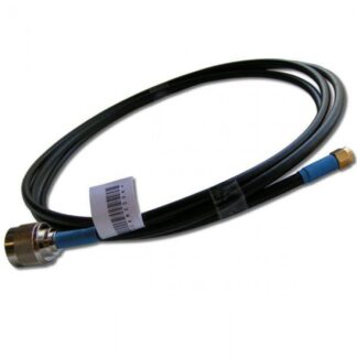
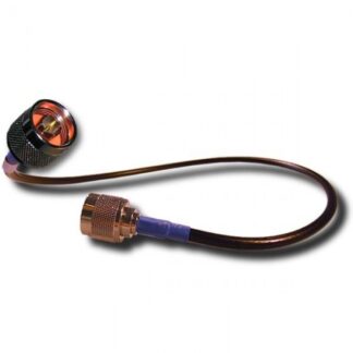
This antenna has four fixed N-female ports and does not include RF feeder cables. Select four low-loss cables with N-male connectors at the antenna end and connectors that match your radio at the other end. Use all four ports for 4×4 MIMO. Accurate alignment and clear line of sight improve directional-link performance. Use of 6 GHz is subject to equipment capability and local regulations.
Technical specifications
| Frequency range | 2400-2500 MHz; 4900-7125 MHz |
|---|---|
| Gain | 10 dBi; 13 dBi |
| MIMO / ports | 4×4 MIMO; 4 ports |
| Polarization | 2x vertical + 2x horizontal |
| Horizontal beamwidth | 55° at 2.4 GHz; 44° at 4.9-7.125 GHz |
| Vertical beamwidth | 50° at 2.4 GHz; 40° at 4.9-7.125 GHz |
| Front-to-back ratio | ≥25 dB |
| Port isolation | ≥28 dB |
| VSWR | <2 |
| Impedance | 50 ohms |
| Maximum input power | 50 W |
| Lightning protection | DC ground |
| Connectors | 4x fixed N female |
| Dimensions / weight | 250 x 250 x 25 mm; 0.7 kg |
| Mounting | Mast Ø30-50 mm |
| Radome | UV-resistant ABS |
| Rated wind velocity | 210 km/h |
| Operating temperature | -40°C to +65°C |
Package contents
- 524WiFi™ directional panel antenna
- Mast-mounting kit
- RF feeder cables are not included
524WiFi™ model: 524WIFI-TPC-2472-13BD
Actual wireless performance depends on the connected equipment, cable losses, installation, radio environment and applicable local regulations.
Directional gain for a known target or service sector
The 524WIFI-TPC-2472-13BD is a four-port outdoor Wi-Fi panel covering 2400–2500 and 4900–7125 MHz. It provides 10 dBi gain at 2.4 GHz and 13 dBi across the 5/6 GHz range, with four N female ports for a compatible 4×4 MIMO radio.
A directional panel is the correct tool when the important radio, building, tower or client area lies in one defined direction. Instead of spending the available RF energy equally around the mast, the panel shapes it into a forward beam and suppresses more energy behind the antenna. That can improve the desired link and reduce reception of unwanted signals outside the service sector.
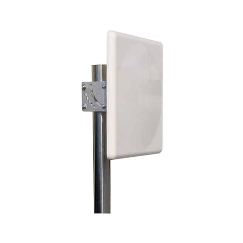
4×4 MIMO with two vertical and two horizontal paths
Two vertical and two horizontal antenna paths create a documented cross-polarized four-port system. Connect all four N female ports through equal, low-loss 50-ohm cables to equipment designed for 4×4 external antennas.
The 250 × 250 × 25 mm ABS panel weighs 0.7 kg and mounts to a 30–50 mm mast. Its flat forward-facing form makes the intended service direction visually clear during installation.
Reading the beam specification before aiming
At 2.4 GHz the horizontal/vertical beam widths are 55°/50°. At 4.9–7.125 GHz they narrow to 44°/40°. The higher-band 13 dBi gain is therefore concentrated into a tighter sector than the 10 dBi low-band pattern.
55° × 50° at 2.4 GHz · 44° × 40° at 4.9–7.125 GHz
Beam width is not an alignment tolerance to ignore. Start with a map or site survey, set azimuth toward the target and then adjust while observing real radio metrics. Final alignment should be based on link quality, not only on a visual compass bearing. Reflections, terrain and building materials can move the best practical direction away from the geometric line.
Forward gain, front-to-back ratio and isolation
Documented forward gain is 10 dBi at 2.4 GHz and 13 dBi at 4.9–7.125 GHz. That is useful for point-to-point bridges, building-to-building links and defined outdoor coverage sectors, provided alignment and legal EIRP are handled correctly.
The front-to-back ratio of at least 25 dB describes the specified difference between the forward region and energy behind the panel. Port isolation of at least 28 dB helps the MIMO paths remain electrically distinct. These values matter together: gain without a useful beam, adequate rear rejection and isolated paths would not provide the same system behaviour.
Directional gain does not create RF power. On transmit it concentrates the radio’s delivered energy toward the sector; on receive it favours signals arriving from that sector. Legal EIRP and equipment limits must be calculated with antenna gain and cable loss included.
524WiFi Signal Plus™ is bidirectional
A passive panel uses the same reciprocal RF structure for reception and transmission. 524WiFi Signal Plus™ identifies the complete documented path: supported bands, forward gain, beam geometry, polarization, impedance, matching, isolation and connectors. It is not an active booster. The real advantage is that the antenna can be selected and aligned from measurable data.
VSWR is specified below 2, impedance is 50 ohms and every path is brought out through a robust N female interface. The 25 dB front-to-back ratio and 28 dB isolation are as important to this model’s Signal Plus profile as the headline gain.
Where this panel is strongest
A defined remote site within the forward beam.
Four-port access points serving a planned yard, venue or campus direction.
A forward pattern that rejects more energy from behind than an omni design.
Choose this 4×4 version for a radio with four compatible external paths and for links where capacity, path diversity and one clean forward sector matter. It is not a substitute for a six-port or two-port antenna; port count must follow the radio.
Alignment and installation workflow
- Confirm the target. Identify the remote radio, base-station sector or intended coverage zone. Record distance, height, obstructions and competing transmitters.
- Match every RF interface. Verify frequency blocks, 4×4 port support, 50-ohm impedance and four N female connectors. Plan low-loss cable and surge protection before mounting.
- Mount on a stable mast. Use the supplied hardware within the documented mast range. The panel face must remain stable under wind; small angular movement matters on a directional link.
- Set polarization and orientation. Keep the panel in its designed orientation so the internal two vertical and two horizontal paths elements operate as specified. Do not rotate casually without understanding the remote system.
- Align using radio metrics. Sweep slowly through azimuth and elevation. Watch signal quality, noise/interference, modulation, throughput and uplink stability rather than one instantaneous strength value.
- Weatherproof and document. Seal exposed connector joints, provide strain relief and drip loops, label every MIMO path, record final angles and photograph the completed installation.
Choosing cable and connectors
N female connectors allow the installer to select cable length and termination for the actual equipment. At 5 and 6 GHz, cable attenuation can quickly consume several decibels of the panel’s gain. Place the radio close where practical or use a properly calculated low-loss feed system.
Use the same cable type and similar length on all MIMO paths. Unequal attenuation changes the balance between ports. Each adapter adds insertion loss and another possible weather ingress point, so prefer a correctly terminated end-to-end cable over a chain of converters. Grounding, bonding and surge protection must follow the connected equipment, structure and local electrical requirements.
Specification guide
- Frequency and gain
- 10 dBi across 2400–2500 MHz and 13 dBi across 4900–7125 MHz. The two ranges cover compatible 2.4, 5 and 6 GHz Wi-Fi radios; the radio still determines standards, channels and legal operation.
- VSWR
- Specified below 2 across the documented bands. Installed matching depends on cables, adapters, connector condition and mounting environment.
- Polarization
- Two vertical and two horizontal paths support the documented 4×4 arrangement and help provide distinct MIMO channels.
- Maximum input
- Maximum input is specified as 50 W per product specification. This is a component rating, not an instruction or legal authorization to transmit at that level.
- Mechanical envelope
- 250 × 250 × 25 mm, 0.7 kg, four N female ports and mast mounting for 30–50 mm diameter.
- Environmental limits
- UV-resistant ABS radome, specified 210 km/h wind rating and −40°C to +65°C operating range. No unstated IP rating is claimed; connector and cable-entry weatherproofing remains essential.
Directional panel or omnidirectional antenna?
Use this four-port panel for a compatible 4×4 radio. If the equipment has only two external ports, the smaller 2×2 TPC-2472-13D is the direct match. If targets surround the site, use an outdoor omni pattern instead.
A directional panel rewards good planning and alignment. If the target direction changes frequently or several equally important sites surround the mast, an omni antenna may produce the more useful network even with lower stated gain. Pattern must match geometry.
Frequently asked technical questions
Does the highest dBi value apply at every frequency?
No. The documented values are 10 dBi in the 2.4 GHz range and 13 dBi from 4.9 to 7.125 GHz. Design each band with its own gain and beam width.
Can I point the panel through a wall or roof?
RF may pass through some materials, but loss and reflections can be severe and frequency-dependent. Whenever possible, create a clear outdoor line of sight. Do not assume that a good 2.4 GHz path will behave identically at 6 GHz.
Will the panel improve both download and upload?
It can improve the passive RF path in both directions when aligned correctly. Actual service remains limited by radio power, remote antenna, network load, modulation, interference and cable loss.
Can fewer than four ports be connected?
Use the antenna with equipment and an operating mode explicitly designed for the available paths. Never transmit into an active unconnected radio port. For a lower port-count radio, select the matching antenna version rather than assuming unused paths add value.
How precisely must it be aimed?
Stay within the forward beam, then optimise against live link metrics. The narrower the beam and the longer the path, the more important a stable mast and fine adjustment become.
Engineering note from 524WiFi™
A high-gain panel performs best as part of a complete link budget. Define the target, match 4×4 ports and polarization, minimise equal-length feed loss, align on quality metrics and validate the return path. The 524WIFI-TPC-2472-13BD provides the documented directional foundation for that work.
Reviews
There are no reviews yet.