
Description
524WiFi Signal Plus™: Four matched paths for true 4×4 MIMO outdoor coverage
Engineered for receive and transmit. 524WiFi Signal Plus™ is our technical designation for an antenna whose frequency range, elements, MIMO ports, 50-ohm impedance, gain and matching are specified as one complete RF system. A passive antenna uses the same reciprocal RF path in both directions: it receives signals and radiates the transmitter power supplied by the connected radio.
Four integrated RF paths provide 360° coverage with 4 dBi gain at 2.4 GHz and 6 dBi across 4.9-7.125 GHz. All four 3 m leads are intended to work together with one 4×4 MIMO radio. This gives installers a specification-led choice instead of a vague one-size-fits-all accessory. It is not an active amplifier and does not create additional transmitter power; the advantage comes from selecting the correct pattern, gain, ports, polarization and connectors for the real installation.
- 4 independent MIMO paths
- 4 / 6 dBi documented gain
- VSWR <1.5 / <2.2
- Four equal-purpose 3 m LMR100 leads
Documented gain by frequency range
Bar lengths are normalized within this product for quick comparison; the printed dBi values are authoritative. End-to-end results also depend on radio power, cable loss, placement, alignment, interference and local network conditions.
524WiFi™ Outdoor Wi-Fi 6E Omnidirectional Antenna, 4×4 MIMO, 2.4/5/6 GHz, 4/6 dBi, 4x RP-SMA Male, 3 m
A four-port outdoor omnidirectional antenna designed for 4×4 MIMO Wi-Fi systems. It covers 2.4 GHz and the extended 4.9-7.125 GHz range, providing all-around coverage from one weather-resistant radome and four long integrated leads for flexible equipment placement.
Key benefits
- 4×4 MIMO with four independent antenna ports
- 2400-2500 MHz and 4900-7125 MHz operating bands
- 4 dBi gain at 2.4 GHz and 6 dBi at 4.9-7.125 GHz
- 360° horizontal coverage around the installation point
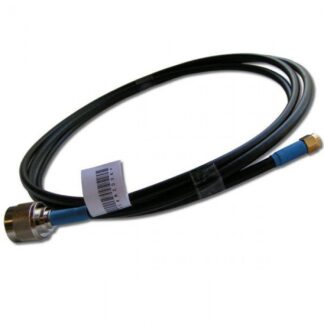
- Four RP-SMA male connectors on 3 m white LMR100 cables
- Outdoor UV-resistant PVC radome and mast mounting kit
Recommended applications
- Outdoor 4×4 MIMO access points and gateways
- Wi-Fi 6 and Wi-Fi 6E infrastructure
- Warehouses, campuses, hospitality and public-area coverage
- Radios with four RP-SMA female antenna ports
Installation and compatibility
Use all four leads with the four antenna ports of one 4×4 MIMO radio. RP-SMA and standard SMA are different connector families. The 3 m integrated cables simplify routing but should not be extended unnecessarily because every additional cable adds RF loss. Use of 6 GHz requires compatible equipment and compliance with local regulations.
Technical specifications
| Frequency range | 2400-2500 MHz; 4900-7125 MHz |
|---|---|
| Gain | 4 dBi; 6 dBi |
| MIMO / ports | 4×4 MIMO; 4 ports |
| Polarization | Vertical |
| Horizontal beamwidth | 360° |
| Vertical beamwidth | 48° at 2.4 GHz; 28° at 4.9-7.125 GHz |
| VSWR | <1.5 at 2.4 GHz; <2.2 at 4.9-7.125 GHz |
| Impedance | 50 ohms |
| Maximum input power | 50 W |
| Lightning protection | DC ground |
| Connectors and cable | 4x RP-SMA male; 3 m white LMR100 |
| Dimensions / weight | Ø128 x 220 mm; 1.4 kg |
| Mounting | Mast Ø30-50 mm |
| Radome | UV-resistant PVC, white |
| Rated wind velocity | 210 km/h |
| Operating temperature | -40°C to +65°C |
Package contents
- 524WiFi™ outdoor omnidirectional antenna
- Four integrated 3 m white LMR100 leads with RP-SMA male connectors
- Mast-mounting kit
524WiFi™ model: 524WIFI-TOF-2472-6DV
Actual wireless performance depends on the connected equipment, cable losses, installation, radio environment and applicable local regulations.
Outdoor omnidirectional coverage built around documented RF values
The 524WIFI-TOF-2472-6DV brings four Wi-Fi antenna paths into one UV-resistant outdoor radome. Each path covers 2400–2500 MHz and 4900–7125 MHz. Documented gain is 4 dBi at 2.4 GHz and 6 dBi across the 5/6 GHz range, providing a clear specification for compatible four-port outdoor access points and gateways.
An omnidirectional antenna is selected when users or remote devices surround the mounting point. Its 360° horizontal pattern avoids the continuous realignment required by a directional antenna and makes the installation useful for yards, campuses, marinas, farms, industrial sites, temporary operations and other areas where clients can approach from several directions. It is not the best choice when every important device is located inside one narrow sector; in that case a directional panel can place more of the available energy toward the target.
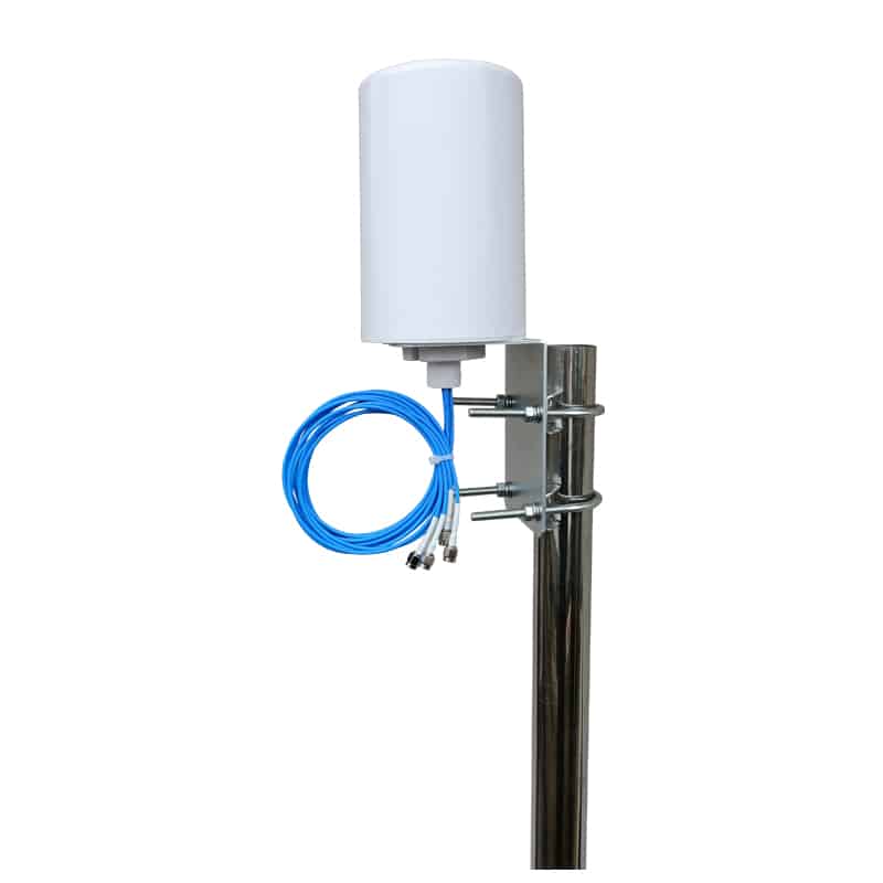
4×4 MIMO, four RP-SMA male leads on 3 m LMR100
This is the purchased custom 524WiFi™ version with four 3 m white LMR100 cables and RP-SMA male connectors. The cable length permits the radio to be installed in a protected enclosure below the antenna, but the complete 3 m feed loss must still be included in the high-band link budget.
Connect all four leads to one correctly documented 4×4 radio. Keep the paths together, avoid sharp bends and label them at both ends so future service does not mix radio-port assignments.
How the radiation pattern shapes real-world coverage
The horizontal beam width is 360°, which describes coverage around the mast. The vertical beam is 48° at 2.4 GHz and 28° at 4.9–7.125 GHz. Imagine a flattened volume of RF energy extending around the antenna rather than a perfect sphere. Mounting the antenna higher can improve line of sight, but excessive height or a poorly chosen vertical pattern can move the strongest energy above or beyond nearby users. Coverage must be planned in three dimensions.
4 dBi at 2.4 GHz · 6 dBi at 4.9–7.125 GHz · four co-located MIMO paths
Install with the antenna vertical and clear of large metal surfaces. Mounting directly beside a steel pole, wall edge, roof plant or solar-array frame can shadow part of the circle and change impedance. Use the supplied mast hardware within the documented diameter range, support every cable independently and create a weather-managed cable route. The outdoor radome and wind rating do not make an exposed connector joint automatically weatherproof; seal outdoor RF interfaces with a professional layered weatherproofing system.
What 4×4 contributes — and what it does not promise
Four antenna feeds support compatible 4×4 equipment and allow the radio to use several spatial paths or diversity mechanisms according to its chipset and firmware. A single housing preserves one common coverage centre and provides a cleaner installation than four separate whip antennas distributed around an enclosure.
MIMO performance is an end-to-end property. The radio must provide the corresponding number of external RF ports, the firmware must use them correctly and the remote device must support compatible spatial operation. The antenna cannot manufacture extra streams, bandwidth or transmitter power. Its job is to provide matched passive RF paths with a known pattern, gain, impedance and connector arrangement.
Connect all active radio paths and keep cable routing consistent. Long extensions, mixed cable types and unnecessary adapters can introduce unequal loss between paths, which reduces the value of a carefully selected MIMO antenna. Where an extension is unavoidable, choose 50-ohm low-loss coax rated for the highest operating frequency and include the complete connector-and-cable loss in the link budget.
524WiFi Signal Plus™ on receive and transmit
524WiFi Signal Plus™ is our specification-led designation for the complete passive RF path. The antenna works reciprocally: on receive it collects energy from remote radios; on transmit it radiates the energy delivered by the connected equipment. The same frequency coverage, pattern, gain, matching and feed system matter in both directions. Signal Plus is not a powered amplifier and does not override the radio’s limits.
The underlying RF values are concrete: 4/6 dBi gain, VSWR below 1.5 at 2.4 GHz and below 2.2 at 4.9–7.125 GHz, 50-ohm impedance and four matched feeds. The custom 3 m cable system is part of the real installed path and should be treated as such during design.
Recommended deployments
Access points and gateways with four documented external RF ports.
Three-metre leads allow separation between the mast antenna and sheltered electronics.
Broad azimuth coverage for users and equipment around the site.
Use this model for higher-order outdoor Wi-Fi systems where the radio genuinely exposes four RP-SMA female antenna ports. It is particularly practical when the radio is mounted in a cabinet or enclosure and the antenna must be positioned above local obstructions.
Site-planning checklist
- Map the clients. Confirm that important devices genuinely surround the antenna. If they occupy one direction only, compare a directional panel before committing to omni coverage.
- Confirm bands and ports. Match the radio’s operating bands, number of external antenna ports, 50-ohm impedance and exact connector gender to this purchased configuration.
- Choose useful height. Seek line of sight over local obstructions without placing the vertical pattern above nearby clients. Analyse both the closest and farthest service points.
- Control feed-line loss. The integrated 3 m LMR100 leads are part of this custom product. Do not add unnecessary adapters or additional cable. Estimate loss at the highest operating frequency, not only at 2.4 GHz.
- Protect the outdoor interfaces. Provide strain relief, a drip loop, connector weatherproofing, grounding and surge protection appropriate to the structure and local electrical rules.
- Measure both directions. Check receive metrics, throughput and stability from representative low-power clients as well as signal strength reported by the client. A strong downlink alone is not a complete wireless link.
Understanding the specification instead of chasing one headline number
- Frequency coverage
- All four paths cover 2400–2500 and 4900–7125 MHz for compatible 2.4, 5 and 6 GHz radios. Local channel availability and legal use remain properties of the connected radio and country configuration.
- Documented gain
- 4 dBi at 2.4 GHz and 6 dBi at 4.9–7.125 GHz. Gain shapes the pattern; it does not create transmitter power or guarantee a fixed distance.
- VSWR
- Below 1.5 at 2.4 GHz and below 2.2 in the high band. Cable, connectors, mounting and surrounding objects all affect the installed system.
- 50-ohm impedance
- Matches the standard RF system impedance expected by compatible radios, connectors and coaxial feed lines.
- DC ground
- Describes the antenna’s specified static/lightning-protection topology. It does not replace building bonding, surge arrestors or a code-compliant lightning-protection design.
- Wind and temperature
- The specified radome assembly is rated for 210 km/h wind and operation from −40°C to +65°C. Correct mast hardware, cable support and connector sealing remain the installer’s responsibility.
Omnidirectional or directional?
Choose this omni model when coverage must extend around the installation point and a single azimuth direction would leave important clients behind the antenna. Choose a directional panel when the remote site, base station or service sector is known and concentrated. A directional antenna can offer more gain and interference rejection toward one target, while an omni antenna offers broader azimuth coverage and easier support for moving or distributed clients.
Compared with the 2×2 version, this product provides two additional paths and longer custom cables for a true four-port installation. Select it only when the radio and network design can use that architecture.
Frequently asked technical questions
Does higher mounting always improve the result?
No. Height can improve line of sight, but the vertical beam must still intersect the client area and longer cable may consume the gain advantage. Select height together with pattern, distance and feed loss.
Can this passive antenna boost transmitter power?
No. It has no active amplifier. Antenna gain describes how the radiation pattern concentrates energy relative to a reference. Legal transmitter power and EIRP remain controlled by the radio configuration and local regulation.
Can unused MIMO leads be left disconnected?
Only if the radio manufacturer explicitly permits that operating mode and the unused radio ports are handled as specified. Never transmit into an active unterminated port. Select the antenna port count that matches the equipment.
Is the antenna automatically compatible with every router?
No. Compatibility requires matching frequency bands, number of external ports, 50-ohm impedance, connector series and gender, and support for external antennas in the device documentation. This configuration terminates in four RP-SMA male connectors; verify four matching RP-SMA female radio ports.
Will the antenna provide the same distance in every direction?
The nominal azimuth pattern is omnidirectional, but the installed environment is not. Buildings, trees, vehicles, terrain, metalwork, cable loss, interference and remote-device capability can create substantial directional differences. A site survey is the correct way to validate coverage.
Engineering note from 524WiFi™
Plan the complete bidirectional link, not only the access-point signal bar. Match the radio ports, account for every metre of feed line, keep the antenna clear of metal, protect the outdoor interfaces and verify uplink from the weakest client. The 524WIFI-TOF-2472-6DV then provides a documented 4×4 omnidirectional foundation rather than an unknown generic aerial.
Reviews
There are no reviews yet.