
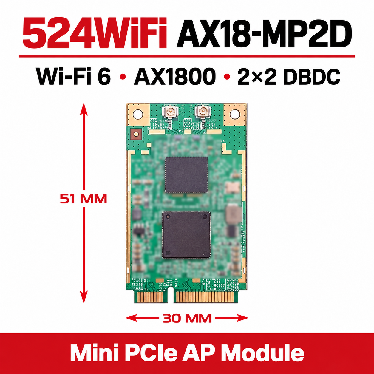
 524WiFi™
AX18-MP2D: Wi-Fi 6 (802.11ax) AP module for engineered deployments
Serve 2.4 and 5 GHz clients simultaneously from one Mini PCIe slot. This AX1800-class Wi-Fi 6 module combines two spatial streams per band with two dual-band antenna connections, making it a compact foundation for OpenWrt access points, IoT gateways and custom routers.
524WiFi™ Pro Plus — tuned for your wireless deployment

Our Pro Plus radio modules are tuned for their intended wireless applications. Combine the radio architecture specified for this model with the right host, software configuration and antenna system to get the most from your installation. The technical sections below explain the settings, interfaces and operating limits relevant to this card.
524WiFi™ Signal Plus™ — make the most of your RF path

Signal Plus™ brings the antenna, operating band, polarization, connectors and installation together as one RF system. Match the antenna coverage to your application and keep the feed path short and low-loss to preserve useful signal in both directions. This model is part of our tuned product range; use its specified RF connector layout and supported bands when building your Signal Plus™ installation.
Actual speed and coverage depend on the complete installation, client capabilities, interference and local operating conditions. Choose antennas and cabling for this card through 524WiFi™; accessories are included only where explicitly stated in the ordered configuration.
Where this module fits
Dual-band OpenWrt access points, gateways, RV/vehicle routers, marine installations and compact appliances that need two concurrent radios from one Mini PCIe slot.
Technical specification
| Wireless generation | Wi-Fi 6 (802.11ax) |
|---|---|
| Performance class | AX1800; theoretical PHY performance class. |
| Radio layout | 2×2 at 2.4 GHz plus 2×2 at 5 GHz, DBDC |
| Supported bands | 2.4 GHz and 5 GHz concurrently |
| Channel widths | 20/40 MHz at 2.4 GHz; 20/40/80 MHz at 5 GHz |
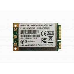
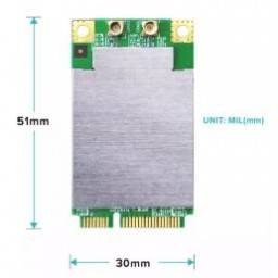
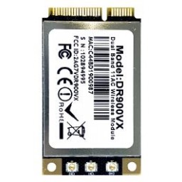
| Host form factor | full-size Mini PCIe |
| Host interface | PCIe |
| RF connectors | 2 × dual-band I-PEX / U.FL-class RF connectors |
| Silicon platform | MediaTek MT7915 |
| Linux driver family | Linux mt76 / mt7915e |
| Power design | 3.3 V ±5%; 3 A host supply recommended |
| Mechanical envelope | 30 × 50.95 mm class; verify keep-out area and mounting screw position against the host drawing. |
| Environmental range | Operating −10 to +70 °C; condensation is not permitted. |
AX18-MP2D engineering notes: radio, host and real deployment
Radio architecture and application
Serve 2.4 and 5 GHz clients simultaneously from one Mini PCIe slot. This AX1800-class Wi-Fi 6 module combines two spatial streams per band with two dual-band antenna connections, making it a compact foundation for OpenWrt access points, IoT gateways and custom routers.
AX18-MP2D — PHY rate by radio configuration
2.4 GHz / 40 MHz / 2 streams: 573 Mbit/s
5 GHz / 80 MHz / 2 streams: 1201 Mbit/s
Deployment design for Mini PCIe
A practical embedded gateway can place low-rate IoT devices on a 20 MHz 2.4 GHz network while laptops use 5 GHz at 80 MHz. Assign guest and trusted SSIDs to separate firewall zones or VLANs in the host OS; the card alone does not create isolation. Test simultaneous traffic on both radios, not just a single laptop download.
OpenWrt driver and firmware selection
Package/stack reference: kmod-mt7915e + kmod-mt7915-firmware. Package names are build references, not a promise that every stable release contains support. Use packages from the exact installed OpenWrt release and target: kernel modules must match the running kernel ABI. Do not force-install a snapshot module onto a stable image. A firmware file loading successfully does not establish that calibration, all bands or AP mode are correct.
Check PCI enumeration first, then firmware loading, then the PHY capabilities and finally hostapd configuration. On minimal images, lspci and iw may need their respective utilities installed. Keep the working image and configuration before changing the software stack. Never overwrite device-specific EEPROM/calibration data with a random file from another radio.
lspci -nnk
uname -r
dmesg | grep -Ei "mt76|mt79|mt7615|firmware|pci"
iw phy
iw reg get
iw dev
logread | grep -Ei "hostapd|wlan|firmware"
In iw phy, confirm AP interface support, band frequencies, channel widths and valid interface combinations. Discover actual interface names with iw dev; names such as wlan0 are not portable between images. Use iw dev INTERFACE station dump with the real AP interface to inspect per-client rates, signal and retries. A missing PHY after successful PCI enumeration points toward driver/firmware initialization rather than the antenna cable.
RF budget and fault isolation
Antenna gain, cable attenuation and legal conducted power form one link budget. In simplified dB terms, EIRP equals radio output plus antenna gain minus feed loss; a higher-gain antenna may require lower radio output under the applicable limit. Also check the return path: improving the AP antenna does not give a phone more transmit power. Compare each chain RSSI to detect an unplugged path or badly positioned antenna, and avoid maximum transmit power as the first response to retries.
For instability under traffic, capture logs before rebooting and compare a cold open-bench test with the closed enclosure. Check supply droop, thermals, firmware resets and the wired uplink. If only wider channels fail, investigate interference, channel availability and client capability before replacing the hardware. For remote sites, retain a wired management or recovery path while qualifying wireless changes.
Configuration documentation and support
Use the OpenWrt wireless configuration guide for general configuration. Revision-specific files and assistance remain through Technical support and firmware guidance. Send the model code, PCB revision, host, country, exact image/kernel version and logs; do not include passwords or private network keys.
Linux, OpenWrt, firmware and board data
The module uses the Linux mt76 / mt7915e stack. Successful enumeration requires a real PCIe connection, sufficient 3.3 V power, a kernel/mt76 combination supporting the silicon generation, matching firmware and—where the platform requires it—the correct board-data/calibration file. Firmware and BDF files are not interchangeable between arbitrary hardware revisions.
- Confirm the PCIe device appears with
lspci -nnbefore debugging the wireless stack. - Review
dmesg | grep -Ei 'mt76|mt79|firmware|pci'for firmware, reset, IOMMU and memory-allocation messages. - Verify loaded modules with
lsmod | grep -E 'mt76|mt79'. - Use
iw phyandiw reg getto confirm supported bands, channel widths and the active regulatory domain.
Use the internal Technical support and firmware guidance area for files we are permitted to host. Contact support with the 524WiFi model code, PCB revision, host board, kernel/OpenWrt release and a complete boot log when a revision-specific package is required.
Installation checklist
- Power off the host, apply ESD precautions and confirm the slot provides PCIe, not only a mechanically matching socket.
- Check the 3.3 V rail against the stated power budget and provide airflow or a correctly fitted heatsink for sustained AP traffic.
- Seat the card without bending it, install the mounting screw and keep metalwork away from components and antenna connectors.
- Attach all required RF paths using the exact connector type: 2 × dual-band I-PEX / U.FL-class RF connectors. Connect and disconnect micro-coax vertically with the proper tool.
- Boot with a supported kernel/firmware set, check PCIe enumeration, then configure country, channel, bandwidth and transmit power legally.
- Run load and temperature tests before closing the enclosure or deploying remotely.
Signal Plus™: antenna and RF-path integration
Signal Plus™ is the 524WiFi™ selection path for matching the correct number of pigtails, low-loss feed length and antennas to the radio layout. Match the complete RF system to the installation and operating country. For this model start from 2 × dual-band I-PEX / U.FL-class RF connectors and 2.4 GHz and 5 GHz concurrently. Keep coax runs short, maintain connector separation and use antennas approved for the intended bands and country.
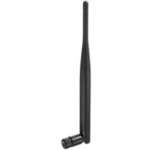
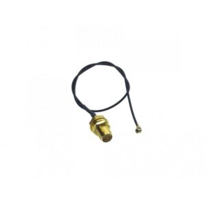
Browse internal RF pigtails and MIMO antennas, then ask us to verify the connector and band combination before ordering a complete RF set.
Troubleshooting quick path
| No device in lspci | Check that the socket carries PCIe, inspect reset timing, seating, power rail and BIOS/device-tree configuration. |
|---|---|
| Firmware load error | Match firmware and board-data files to the driver and hardware revision; do not mix packages from another card. |
| Radio missing a band | Check the selected radio mode, firmware, country code, antenna mapping and whether the model is DBDC or selectable-band. |
| Unstable under traffic | Measure 3.3 V droop and temperature, add cooling, shorten RF feeds and review PCIe/IOMMU errors. |
| Low throughput | Verify negotiated channel width, client stream count, interference, antenna polarization, regulatory power and CPU/network bottlenecks. |
FAQ
What platforms is this card designed for?
Embedded access points, Linux gateways and specialist networking hosts with the specified PCIe interface, power supply and RF connections.
What does Pro Plus bring to this product?
A tuned professional radio platform with model-specific integration guidance, RF-system selection and access to our technical support.
Does Signal Plus™ include antennas?
Antennas and pigtails are included only when explicitly listed in the ordered RF kit. Use the internal antenna and pigtail links to build a verified set.
Can 524WiFi™ supply firmware?
We provide or mirror files only when licensing and revision control allow it. Some firmware is distributed through Linux/OpenWrt packages; some board data is host- or revision-specific.
What information should I send for compatibility review?
Send the exact 524WiFi model code, host board, slot wiring or schematic, available 3.3 V current, kernel/OpenWrt version, intended bands/country, enclosure and antenna plan.
Final model identification and code table
Use this table when comparing the product, preparing a purchase order or requesting integration support. The naming grammar is fixed across the complete 524WiFi™ professional radio-module family.
| Model | 524WiFi AX18-MP2D |
|---|---|
| Generation and speed token | AX1800 identifies the Wi-Fi 6 (802.11ax) performance class. The number denotes its theoretical PHY performance class. |
| Mechanical interface token | full-size Mini PCIe over a PCIe host connection. Use a socket with the specified PCIe wiring, power budget and mechanical clearance. |
| RF-layout token | 2×2 at 2.4 GHz plus 2×2 at 5 GHz, DBDC; 2 × dual-band I-PEX / U.FL-class RF connectors. Use these details to match the antenna feeds and host interface. |
| Full code meaning | AX18 = Wi-Fi 6 / 1800 Mb/s combined class; MP = Mini PCIe; 2 = two spatial streams per band; D = dual-band dual-concurrent; Pro Plus = tuned professional product series. |
| Product series | Pro Plus. Select the host interface, radio layout and RF connectors specified for this model. |
| Ordering SKU | 524WIFI-AX18-MP2D-PP |
| GS1 EAN-13 | 8594158775832 |


Reviews
There are no reviews yet.