
Posted on — Leave a comment

How to Design a Reliable Long-Range Wireless Link for Agricultural Drones (WiFi 6/7 Selection Guide)

If you’ve deployed drones for crop spraying, field mapping, or orchard inspection over any real distance, you’ve probably run into this: the link holds fine at 200 meters, then starts dropping commands or breaking up video well before you hit the range the datasheet promised. It’s rarely a bad chip. It’s almost always an architecture problem.

This guide walks through why long-range agricultural links behave differently from indoor or short-range WiFi deployments, what actually determines reliability at range, and how to select hardware — control-side and video-side — that holds up in the field.

Why Agricultural Drone Links Are a Different Problem

Most WiFi hardware is designed and benchmarked for indoor, short-range, high-density environments — offices, warehouses, retail. Agricultural drone deployments invert almost every one of those assumptions:

  • Distance is the default, not the exception. A single control link routinely needs to cover several hundred meters to a few kilometers across open farmland or orchards.
  • There’s no multipath to lean on. Indoor WiFi benefits from reflections off walls and ceilings. Open fields don’t offer that — and offer very little shielding from other interference either.
  • Control and video have opposite requirements. Control commands are small, frequent packets that need low, consistent latency and near-zero loss. Video (especially 4K, multispectral, or thermal payloads) needs sustained bandwidth and can tolerate some jitter. Serving both well on one link is hard.
  • One-to-many is common. A single ground station frequently needs to manage multiple aircraft flying formation or covering different zones of the same field, which means the AP side has to handle concurrent, fast-moving clients — not a single static link.
  • Power is capped by regulation, not by ambition. ISM-band transmit power and antenna gain both have legal ceilings. You can’t out-power your way to more range.

The Five Things That Actually Determine Reliability at Range

1. Band Strategy: Split the Link, Don’t Pick One Band

2.4GHz diffracts better around terrain, crops, and structures, which is why it’s traditionally the default choice for long-range control links. 5GHz and 6GHz offer far more spectrum and fewer competing signals, which is exactly what high-resolution video needs.

The reliable pattern in the field isn’t choosing one band for everything — it’s running a split architecture: control on 2.4GHz, video on 5GHz or 6GHz. That’s a strong argument for radio hardware where the band configuration is flexible (single-band, dual-band, or switchable tri-band) rather than fixed to one band at the factory.

2. Modulation and Spatial Streams: Know What They Actually Control

Specs like 4096-QAM and multi-stream MU-MIMO are real and useful — but they define your near-field ceiling, not your far-field floor. As distance increases and signal-to-noise ratio drops, the link automatically falls back to lower-order modulation regardless of the chip’s peak capability.

When evaluating hardware for a long-range deployment, the number that matters isn’t the “Gbps peak” on the datasheet. It’s the rate-adaptation curve under low SNR, and specifically the minimum usable data rate at the outer edge of your intended range. That’s the number that tells you whether video will break up or commands will get dropped when the aircraft is farthest from the ground station — which is exactly when you need the link most.

3. MLO (Multi-Link Operation): Redundancy, Not Traffic Splitting

WiFi 7 introduced Multi-Link Operation, which lets a device establish links across multiple bands or channels at once. There’s a common misconception worth clearing up here: MLO isn’t a way to route control traffic on one band, video on another, and backhaul on a third, each running independently.

What MLO actually does is transmit the same data redundantly across multiple links simultaneously, so that if one link momentarily fades or gets interfered with, the other link covers for it — improving reliability and reducing effective latency. For agricultural drones, where a lost link is often the trigger for a return-to-home failsafe, that kind of redundancy has real operational value, not just a spec-sheet checkbox.

4. Topology: Point-to-Point vs. One-to-Many

A single aircraft doing long-range mapping or inspection is often best served by a point-to-point link — a directional antenna setup trading beamwidth for range and stability. But if a ground station needs to manage multiple aircraft or ground terminals simultaneously, the AP side needs OFDMA multi-user scheduling and fast roaming/handoff behavior, or you’ll see queuing delay whenever multiple aircraft check in around the same time.

Know which problem you’re actually solving before you pick hardware — they call for different radio capabilities.

5. Form Factor: Airborne and Ground-Side Needs Diverge

The airborne side is constrained by payload weight and available power, so it needs a small, low-power radio module that can be integrated directly into a flight controller or gimbal payload — with just enough band flexibility to serve the control link without unnecessary weight or draw.

The ground station side is a different design problem entirely: it needs to aggregate multiple client connections, handle higher sustained throughput, and typically needs wired backhaul (Ethernet, sometimes 10GbE) to move the collected video and telemetry off to a local server or the cloud. That usually points toward a board-level platform rather than a compact module.

Mapping Hardware to the Problem

Once you’ve worked through the five factors above, hardware selection becomes a matter of matching platform to role rather than chasing a single “best” spec sheet.

Airborne / terminal-side radio module. You want something small, power-efficient, and configurable — ideally a module where you can select or trim the band configuration (single-band 2.4GHz for a dedicated control radio, or dual-band where the payload allows) without carrying unused radio hardware and power draw. This is the role a WiFi 7 M.2 module built on a chipset like Qualcomm’s QCN9274/QCN6274 platform is designed for, with configurations spanning single-band, dual-band, and 4×4 single-band variants depending on what the airframe needs.

Ground-station aggregation board. This is where you want a flagship-class multi-band platform — four simultaneous bands, wide channels (up to 320MHz), high-order modulation (4096-QAM), multiple M.2 slots for additional radio cards, and dual 10GbE-class wired uplinks. This tier handles concurrent multi-aircraft connections, dynamic channel selection (AFC) to work around interference, and reliably backhauling the aggregated video streams to wherever they’re processed.

Edge gateway with onboard compute. For deployments where you want to do video processing or stream aggregation closer to the field — rather than pushing everything raw to the cloud — a tri-band gateway platform with high-speed wired I/O (dual 10GbE + multiple 2.5GbE) and an onboard AI accelerator tuned for networking workloads is the better fit. It handles wireless backhaul while also doing local compute, cutting the bandwidth pressure on the uplink.

A Practical Decision Order

When you’re actually speccing a system, work through it in this order:

  1. Point-to-point or one-to-many? This determines whether OFDMA and fast roaming on the ground-station side are must-haves or nice-to-haves.
  2. Does the control link need to be physically separated from the video link? This determines whether a single-band module or a multi-band board is the right call for each end of the system.
  3. What are the payload’s power and space constraints? This determines module-level vs. board-level hardware on the airborne side.
  4. Does the back end need edge compute or multi-stream video aggregation? If yes, prioritize a gateway platform with onboard AI acceleration and high-speed wired I/O.

FAQ

Is 2.4GHz or 5GHz better for a long-range drone control link? 2.4GHz generally holds up better over distance and around obstructions like terrain or crop canopy, which is why it’s the more common choice for the control link specifically. 5GHz and 6GHz are typically reserved for the video link, where the extra bandwidth matters more than raw range.

Do I need WiFi 7, or is WiFi 6 enough? It depends on whether you need MLO’s link redundancy and whether your video payload actually needs the extra bandwidth WiFi 7’s wider channels provide. Many long-range control links work fine on WiFi 6; WiFi 7 becomes more valuable as video resolution, aircraft count, or reliability requirements increase.

What’s the actual benefit of MLO for a drone link? Redundancy. The same data is sent across multiple links at once, so a momentary fade on one link doesn’t cost you the connection — it isn’t a way to assign different traffic types to different bands independently.

Should the airborne radio and the ground-station radio be the same hardware? No — they’re solving different problems. The airborne side prioritizes size, weight, and power; the ground station prioritizes aggregate throughput, multi-client handling, and wired backhaul capacity.


If you’re evaluating or redesigning the wireless subsystem in a drone flight-control or video-transmission stack — or migrating an existing deployment from WiFi 5/6 to WiFi 7 — reach out to info at 524wifi.com or .net. We build radio hardware across all three tiers described above and can walk through the specifics of your deployment.
Posted on

QCA9880 to QCN9274/QCN6274: A WiFi 5 to WiFi 7 Module Selection Guide — 524WiFi 600VX / 900VX and DR9274E-TB Compared

From QCA9880 to QCN9274/QCN6274: A WiFi 5-to-WiFi 7 Module Selection Guide — 524WiFi 600VX / 900VX, and DR9274E-TB Compared

For years, the Qualcomm-Atheros QCA9880 has been the default chipset behind a lot of industrial WiFi 5 designs — routers, CPEs, access points, embedded gateways. It’s mature, well-documented, and easy to source, which is exactly why so many product lines are still built around it. But the ground is shifting. As more networks have to handle a pile of devices talking at once — robot fleets on a warehouse floor, banks of industrial cameras, multiple video streams heading back to a controller — WiFi 5’s two crowded bands start to show their age, and WiFi 7 platforms have gotten mature enough to be a real option instead of just a roadmap item.

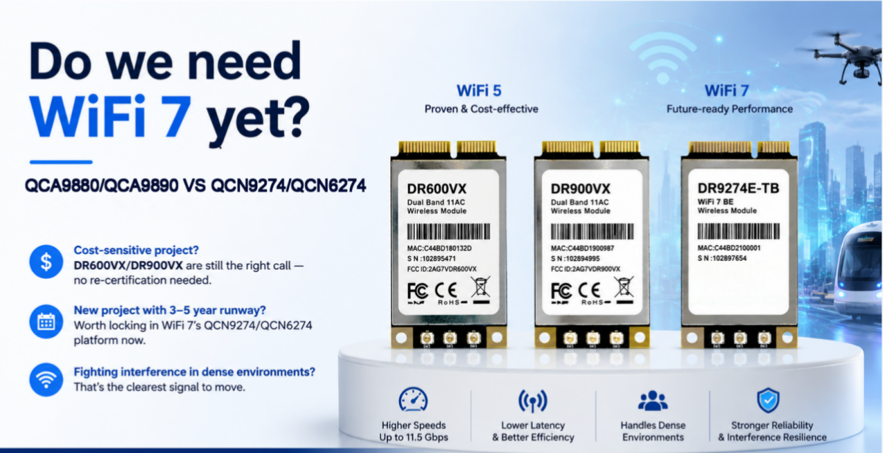
We get this question a lot from customers still speccing hardware around QCA9880: is it time to move, and if so, to what? Below is a practical comparison of two of our QCA9880 modules, 524WiFi 600VX / 900VX Pro+, against DR9274E-TB, which runs on Qualcomm’s newer QCN9274/QCN6274 platform.

The three modules

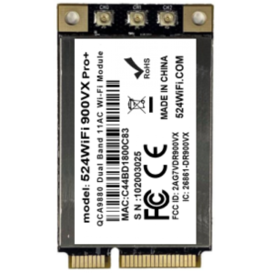
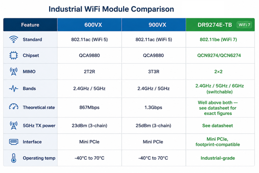
524WiFi 600VX Pro+ and DR600VX are a 2×2 MIMO 802.11ac module — 2T2R, theoretical throughput up to 867Mbps. Two UF.L antenna connectors, 2.4GHz and 5GHz (including 4.9GHz), TX power up to 24dBm/23dBm, Mini PCIe interface, -40°C to 70°C operating range. It’s a small board — 30.0 × 50.9 × 3.2mm — and it’s been a workhorse for cost-sensitive designs that don’t need a third antenna chain.

524WiFi 600VX Pro+ and DR600vx – QCA9880 2X2

524WiFi 600VX Pro+ and DR900VX are the same chipset, same footprint, same pinout — but 3×3 MIMO instead of 2×2, pushing theoretical throughput to 1.3Gbps and TX power up a couple of dB (26dBm/25dBm) thanks to the extra chain. There’s also a DR900VX-i variant on QCA9890 rated for 85°C, and a DR900VX-4.9 with 4.9GHz support. Because the mechanical and electrical interface is identical to DR600VX, swapping between the two mostly comes down to whether your enclosure has room to route a third antenna.

524WiFi 900VX Pro+ and DR900vx – QCA9890 3X3

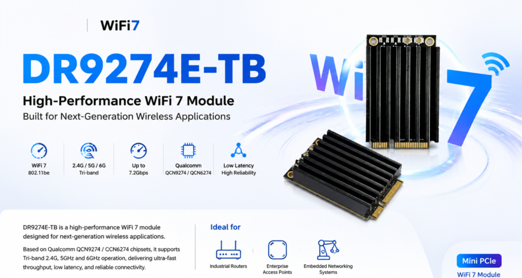
DR9274E-TB is a different generation entirely. It’s built on QCN9274/QCN6274 and supports WiFi 7 (802.11be) across three bands — 2.4GHz, 5GHz, and 6GHz. Worth being precise here: it’s tri-band switchable, meaning the module picks the best band to operate on, not three bands running separate traffic simultaneously. It’s a 2×2 MIMO design, Mini PCIe, and mechanically compatible with existing WiFi 5 module footprints, so it’s aimed at the same kinds of products — industrial routers, enterprise APs, outdoor CPEs and bridges, mesh systems, edge AI platforms — just with more headroom.

Side by side

QCA9880 VS QCN9274

What actually changes

Going from 2T2R to 3T3R (600VX to 900VX) is a fairly straightforward upgrade — one more spatial stream, a bit more throughput, and a bit more stability in multipath environments, since the extra chain gives the radio more to work with. If your enclosure has the space and the budget allows it, 524WiFi 900VX Pro+ is the easy call.

The jump to WiFi 7 is a different kind of change, and it’s not really about raw speed. The number that matters most is 6GHz — an almost entirely clean band with none of the legacy congestion that 2.4GHz and 5GHz have accumulated over a decade of deployments. In a warehouse or factory environment with dozens of APs and client devices fighting for airtime, that alone can matter more than any Mbps figure on a spec sheet. WiFi 7 also brings multi-link operation, which lets a device coordinate traffic across bands rather than being locked to one — though how much of that you actually get depends on chipset support and firmware, so it’s worth checking specifics for your use case rather than assuming every feature is turned on out of the box.

None of this means everyone needs WiFi 7 today. A lot of deployments — point-to-point links, smaller networks, applications without dozens of devices packed into one space — are still perfectly well served by QCA9880. The cases where it’s worth moving now are the ones already running into interference or density problems, or new designs with a long enough runway that the 6GHz advantage will keep paying off for years.

Which one fits your project

If you’ve already built a product around QCA9880 — PCB layout done, drivers sorted, certifications in hand — there’s usually no reason to change anything. 524WiFi 600VX Pro+ and 524WiFi 900VX Pro+ share a footprint and pinout, so you can pick between them based on cost and available antenna space without touching your certification.

If you’re starting a new design with a multi-year lifecycle ahead of it, DR9274E-TB is worth a serious look even though WiFi 7 silicon costs more up front. QCA9880 is an older chipset generation at this point, and long-term sourcing risk tends to creep up as a platform ages. Locking in 6GHz early also means you’re not scrambling to redesign in a couple of years when everyone else has already made the jump.
And if you’re already seeing throughput drop off or latency get jittery once you cross a certain device count — a common story with AMR fleets, multi-camera vision setups, dense AP coverage — that’s usually a clearer signal than any roadmap discussion. Tri-band switching, combined with sensible planning around which traffic goes where, tends to ease that bottleneck in a way a WiFi 5 dual-band design just can’t.

Bottom line

  • Sticking with an existing QCA9880 design, watching cost closely → 524WiFi 600VX or 524WiFi 900VX Pro+
  • New project, long lifecycle, want to be ahead of the spectrum curve → DR9274E-TB
  • Already fighting interference or density issues → DR9274E-TB

Every deployment is a little different, and the right call depends on your device density, antenna space, budget, and how long the product needs to stay in the field. If you want to talk through your specific case, or need test data, samples, or custom development — antenna layout, firmware tuning, OEM/ODM support — reach out info at 524wifi.net .
Posted on

IPQ5018 | 524WiFi and Wallys DR5018S VLAN Configuration Guide

1. Introduction

The 524WiFi and Wallys DR5018S router board, based on the Qualcomm IPQ5018 chipset, is widely used in industrial wireless applications. VLAN functionality allows network segmentation, optimized traffic management, and enhanced security. This guide provides a step-by-step tutorial to configure Access VLAN and Trunk VLAN on the DR5018S.

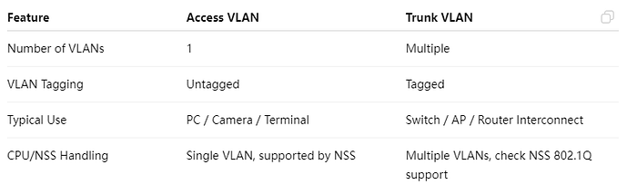
2. Understanding VLAN, Access, and Trunk

Article content

Access VS Trunk

3. Prerequisites

  • Wallys DR5018S router, firmware: wallys firmware
  • Admin access via Web GUI or SSH
  • VLAN ID plan and IP addressing plan
  • Optional: VLAN-aware NIC or Vlan Switch for testing

4. VLAN Configuration on DR5018S

Steps:

  1. Log in to the Web GUI.
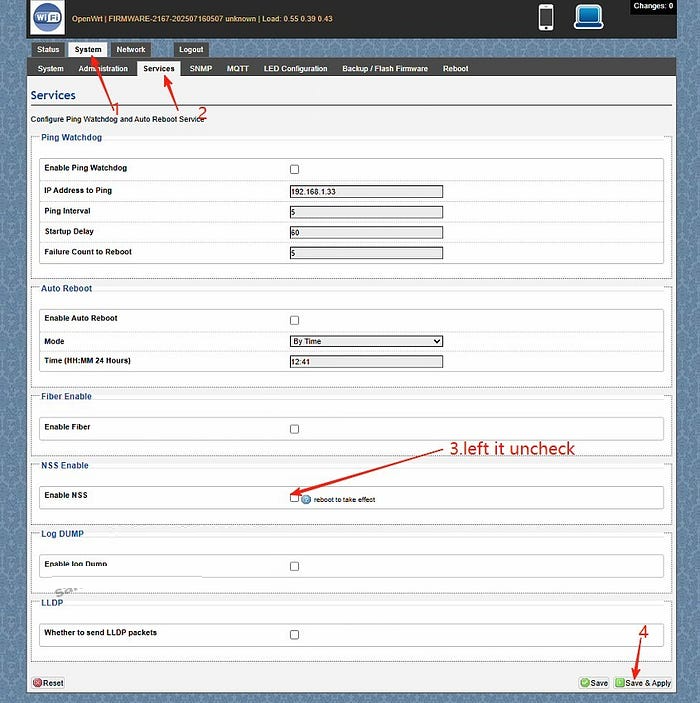
  2. Go to System → Services. Left the Enable NSS uncheck and click “save and apply”
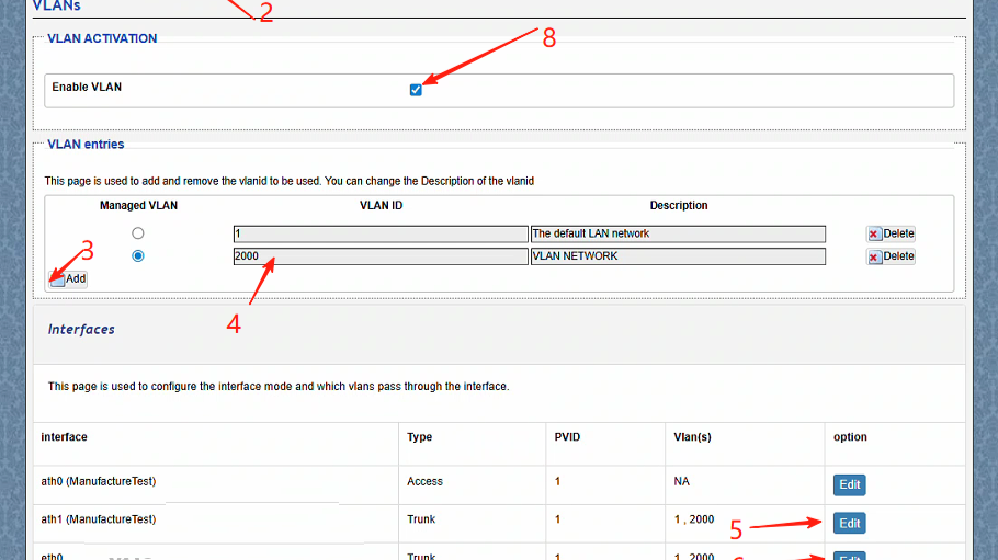
  3. Go to Network → Vlans.Create a VLAN (e.g., VLAN 2000).
  4. Edit the ath1(the working radio) and eth0(the ethernet port connected) port mode to Trunk.
  5. ath1 setting:Select type Trunk,Assign the PVID as 1,select Vlans 2000,save changes
  6. ath1 setting:Select type Trunk,Assign the PVID as 1,select Vlans 2000,save changes.
  7. Assign an IP address to the VLAN interface (static or DHCP).
  8. Save and apply the configuration.
  9. Test connectivity: connect a PC to the port, get an IP, and ping the radio.

5. Troubleshooting

  • Cannot access the device → check VLAN ID, PVID, and tagging.
  • Trunk traffic lost → verify VLAN configuration on the remote end.
  • PC cannot ping → ensure the IP address is in the VLAN subnet.
  • Check NSS hardware acceleration

With this guide, you can easily configure Access VLAN and Trunk VLAN on the DR5018S router board. VLANs help isolate traffic, improve security, and optimize performance in industrial wireless networks.

For more technical support and inquiry for industrial wireless products, contact 524WiFi at info@524wifi dot com or net!

Posted on

Your Go-To Guide for Loading Firmware and Configuring MLO on QCA DR9574 IPQ9574 !

Your Go-To Guide for Loading Firmware and Configuring MLO on IPQ9574 !

Hey there! Are you feeling a bit lost when it comes to loading firmware and configuring MLO on the IPQ9574? Fret not! Here at 524WiFi, we’ve crafted a super easy and detailed tutorial just for you. Let’s jump right into it!

Why This Guide?

Whether you’re a seasoned pro or a complete newbie, setting up advanced hardware can be daunting. That’s why we’re here to break it down into simple, manageable steps. By the end of this guide, you’ll be a pro at loading firmware and configuring your device like a champ!

What You’ll Get

  • Clear Hardware Setup: We’ll kick things off by connecting the hardware. Don’t worry; we’ll guide you through the process of connecting your UART cable without any hassle.
  • Seamless Firmware Loading: Next, we’ll tackle loading the firmware. We’ll ensure you have everything in the right place and give you step-by-step instructions to make it a breeze.
  • Effortless AP Configuration: Finally, we’ll walk you through configuring the Access Point. This step is crucial for ensuring your device runs at its best.

Stick Around for More!

But wait, there’s more! If you stick around until the end of the video, you’ll get an exclusive sneak peek at our upcoming DR9574kit throughput test. Trust us, you won’t want to miss it!

Ready to Dive In?

So, what are you waiting for? Click the link below to watch our tutorial and empower yourself with the skills to conquer firmware loading and MLO configuration!

📺 Watch here:

P.S.: The MLO for DR5332/DR5322 is currently in active preparation. We appreciate your patience as our R&D team works diligently on this. Stay tuned for the latest updates coming your way soon—just you wait!

Posted on

How to Enable DR9074-Triband Functionality on Linux 5.17.0: Step-by-Step Guide

This tutorial builds upon the previous one and provides additional information on:

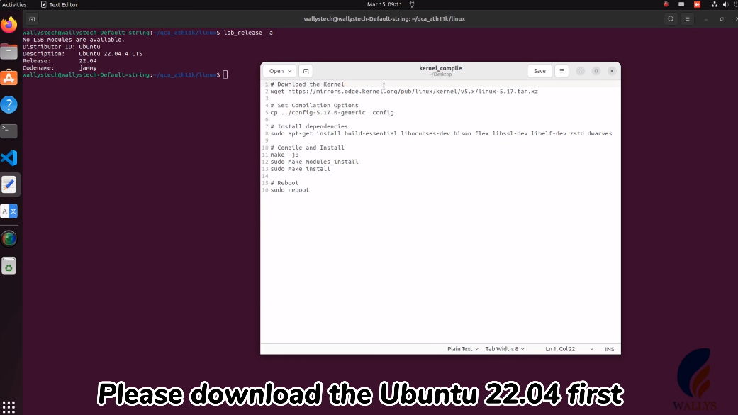
1.How to download Ubuntu 22.04.

2.How to compile the 5.17 kernel to support ath11k.


524WiFi recently announced the compatibility of DRiver m. module DR9074-TRIBAND with ATH11K on Linux, expanding its support beyond Qualcomm platforms to various Linux embedded systems, including Ubuntu. In this guide, we’ll walk you through the process of loading the driver for DR9074-Triband on Linux 5.17.0, demonstrating its seamless integration with ath11k. The module is showcased to function effectively in both AP (Access Point) and STA (Station) modes across the 2.4GHz, 5GHz, and 6GHz bands.

Introduction to DR9074 (QCN9024):

DR9074-Triband, equipped with the Qualcomm Atheros QCN9024 chipset, is an advanced enterprise wireless module. It incorporates a 4×4 MU-MIMO Dual Band Wireless Module, tailored for mobile access in high-bandwidth applications such as video streaming, voice communication, and data transmission. Key features include a maximum power of 23 dBm per chain, supporting data rates up to 4949Mbps. Operating in Tri-Band (2.4GHz, 5GHz, and 6GHz) with 4×4 WiFi 6E (802.11ax) and 4 spatial streams, it features an M.2 E Key Interface and PCI Express 3.0 Interface. Applications span security surveillance, commercial radio coverage, hotel wireless setups, and specialized scenarios.

Device Specifications:

  • Chipset: Qualcomm Atheros QCN9024
  • WLAN Host Interface: PCI Express 3.0
  • Frequency Range: 2.412GHz-2.472GHz & 5.18GHz-5.825GHz & 5.925GHz-7.125GHz
  • Data Rates: Maxim 23dBm per chain, up to 4949Mbps
  • Channel Spectrum Widths: Support 20/40/80/160MHz
  • Modulation Techniques: OFDMA, including BPSK, QPSK, DBPSK, DQPSK, 16-QAM, 64-QAM, 256-QAM, 1024-QAM, 4096-QAM
  • Temperature Range: Operating: -20°C to 70°C, Storage: -40°C to 90°C
  • Humidity: Operating: 5% to 95% (non-condensing), Storage: Max. 90% (non-condensing)
  • Certification: TBD
  • Reference Design: PN02.7
  • Power Consumption: TBD
  • Dimensions (WxHxD): 57mm x 63mm x 6mm

Device Setup:

  • PC with Linux 5.17.0
  • Adapter card (1pc)
  • DR9074-Triband (1pc)

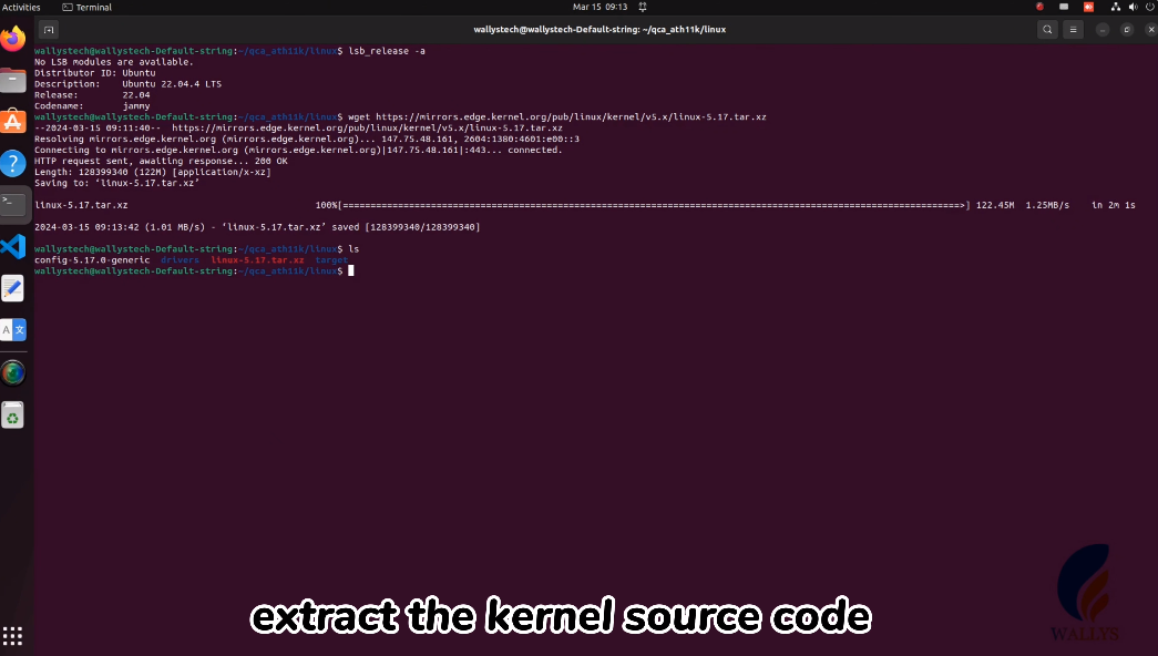
1.Downloading the Ubuntu 22.04 version.

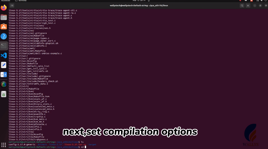
2.Compiling kernel version 5.17.0 to include support for ATH11K 9074

Driver Loading Steps:

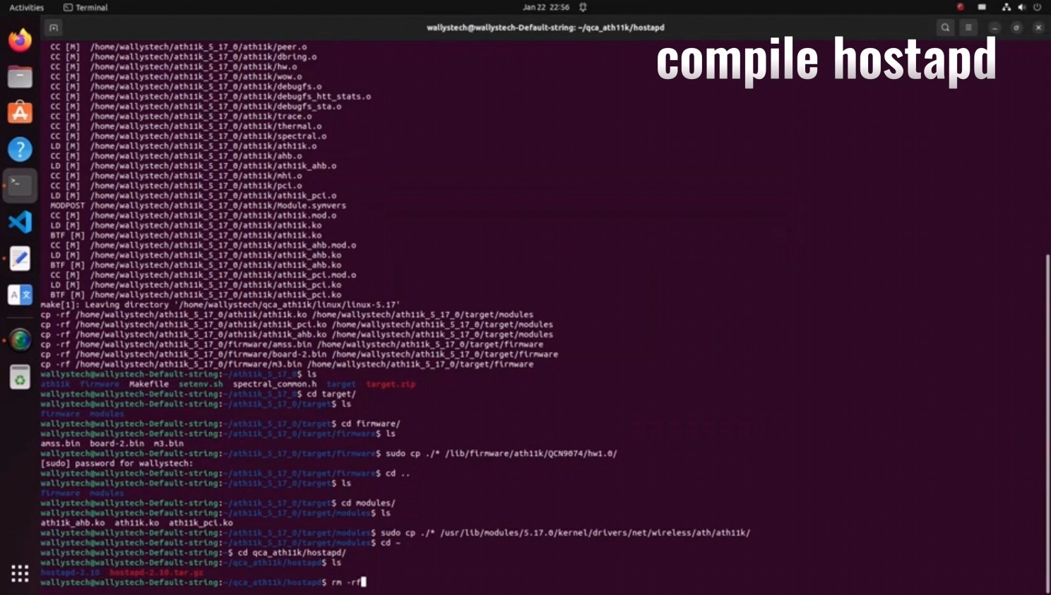
Compile the driver.

Navigate to the firmware folder and copy the card firmware.

Copy the compiled driver to the designated path.

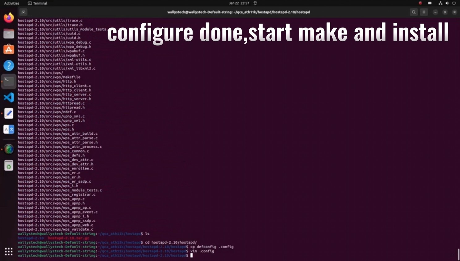
Compile hostapd.

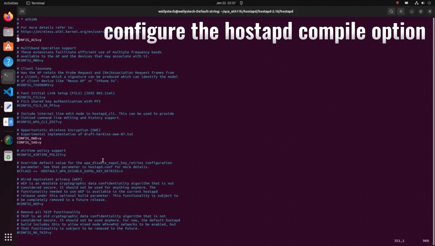
Configure hostapd compile option

Complete configuration, commence making, and install.

Verify the successful installation of the current version, then run hosta

d.

Confirm the presence of the DR9074 card.

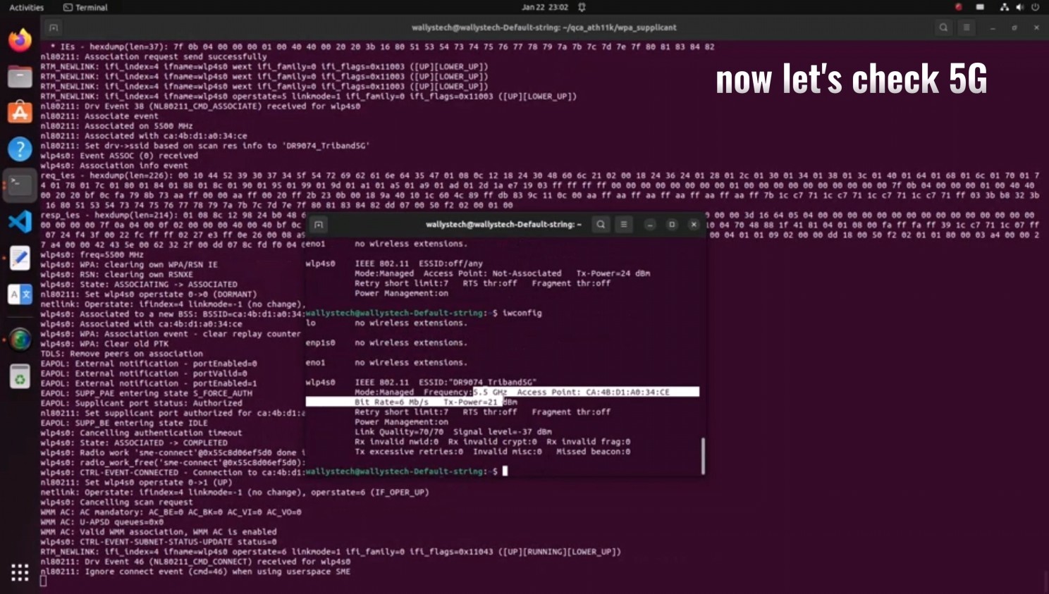
Validate the functionality of 2.4G/5G/6G under AP mode.

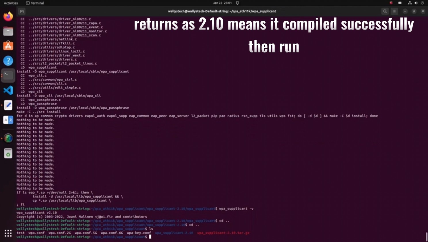
Compile the tool for STA mode and configure compile options.

Finish compilation, check the version (returns as 2.10 for successful compilation), then run.

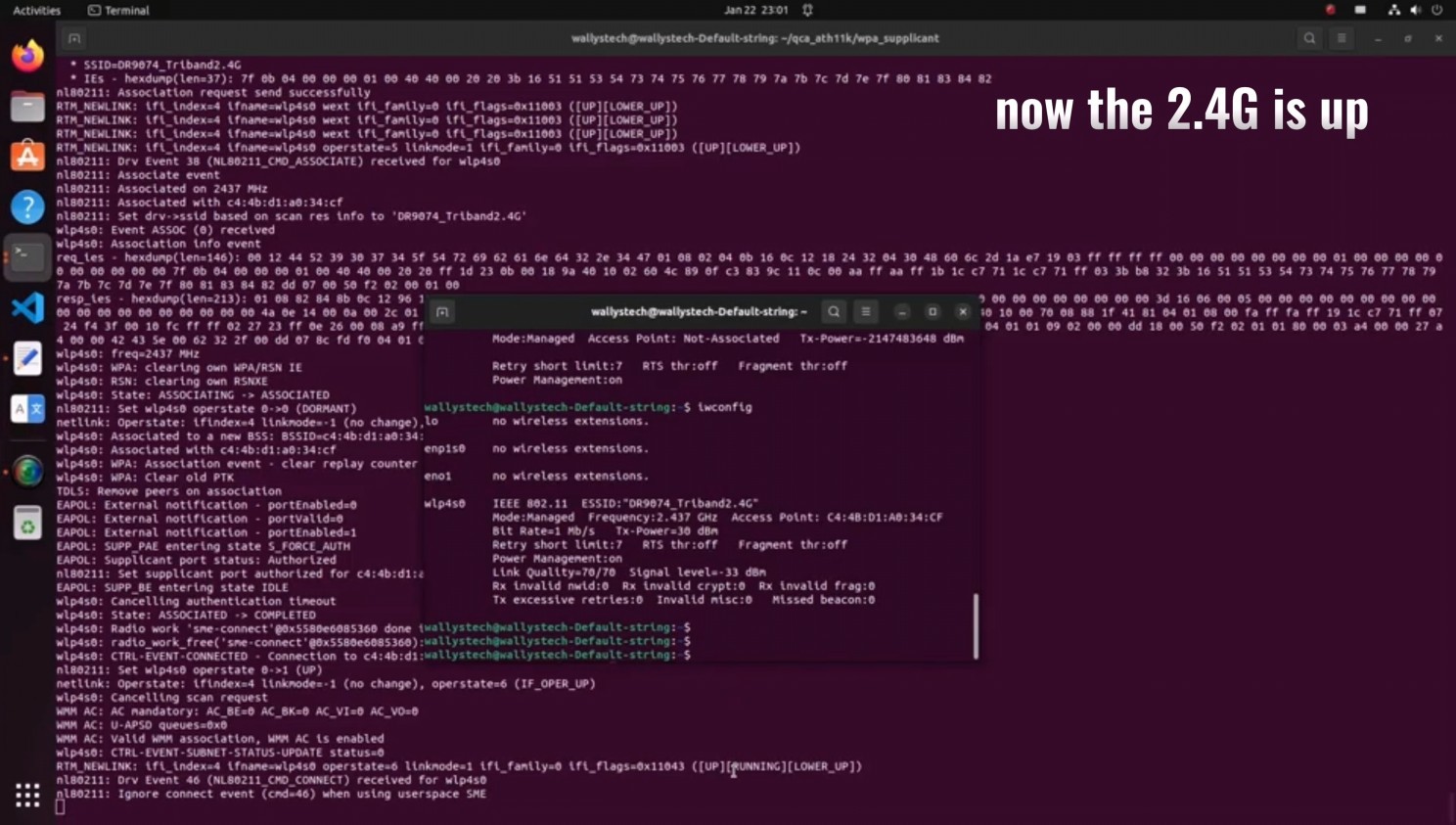
Confirm the functionality of 2.4G/5G/6G under STA mode

Thank you for reading 🙂 We hope that this can help to many customers.

Posted on

MT 7916 porting guide for OpenWRT


MT 7916 porting guide for OpenWRT on AP7621 platform

1. Compile OpenWRT


1-1. Host Enviromnemt

OS: Ubuntu 22.4.1 LTS


1-2. Install utilities for compiling


Execute following command in terminal:


sudo apt update

sudo apt upgrade

sudo apt install build-essential clang flex g++ gawk gcc-multilib gettext git

libncurses5-dev libssl-dev python3-distutils rsync unzip zlib1g-dev pkg-config

1-3. Clone Source Code and Update


Clone the main branch and update it
git clone https://git.openwrt.org/openwrt/openwrt.git
cd openwrt
./scripts/feeds update -a
./scripts/feeds install -a


1-4. Menuconfig Setting


make menuconfig


Select the following setting:


Target System: MediaTek Ralink MIPS
Subtarget: MT7621 based boards
Target Profile: AP7621-001

Include the following features:


Kernel modules/Wireless drivers/kmod-mt7916-firmware
Kernel modules/Wireless drivers/kmod-mt76x2
Kernel modules/Wireless drivers/kmod-mt7915e
Kernel modules/Wireless Drivers/kmod-cfg80211
Kernel modules/Wireless Drivers/kmod-mac80211
(*optional for ap)Network/WirelessAPD/wpad
(*optional for ap)Network/WirelessAPD/hostapd-common
(*optional for iw tools)Base system/wireless-tools
(*optional for web server)LuCI/Collections/luci
(*optional for web server)LuCI/Collections/luci-ssl

1-5. (*optional) Turn on wireless ap in default


Revise the file /openwrt/package/kernel/mac80211/files/lib/wifi/mac80211.sh


set wireless.${name}.disabled=0

Save and compile.

1-6. Compile


make -j $(nproc) kernel_menuconfig

make -j $(nproc) defconfig download clean world V=s

2. Starting AP7621 platform for verify


After burning and booting your AP7621, you can check the interface on OpenWRT by the command:

ifconfig -a

and test the connection by ping.

View All Tags

Posted on

ZBT WG1608 4G 5G LTE router users setup configuration installation guide

USER FRIENDLY INSTALLATION MANUAL FOR

ZBT WG1608, ZBT WE1326, ZBT WG3526 4G 5G LTE ROUTERS

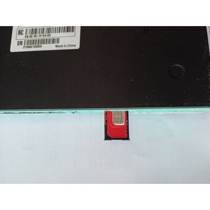
  1. Put a functional SIM card into the SIM slot (please see picture bellow).
  2. Please bear in mind that there are 2 types of antennas: LTE and WiFi. Be sure that you’re putting in the right antenna to the right slot, You can recognize them by female and male connectors.
  3. After ensuring that everything is in the right place, please first connect your LAN port then the routers DC interface, please use 12V / 2A power adapter.
  4. Now type into your browsers URL query “192.168.1.1” it’ll take you to the routers firmware

            Passwords are: Viper firmware “Password1234” or “admin” for OpenWRT

            WiFi default password: Viper firmware “LakeWater561” , in OpenWRT firmware is WiFi without encryption by default.

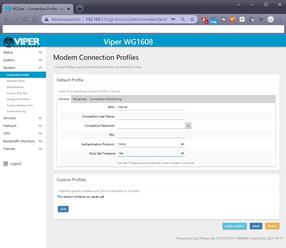
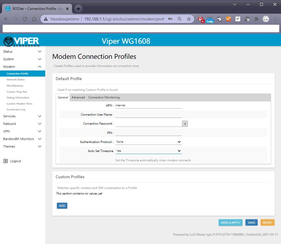
  1. After getting inside your firmware please go to “Modem > Connection profile” and set your APN to “internet” or other APN from your provider and wait at least 5 minutes.

A few of the more common carrier APNs are listed below:

AT&T = BROADBAND
Verizon = VZWINTERNET
T-Mobile = FAST.T-MOBILE.COM
Sprint = R.ISPSN (or, N.ISPSN on some)

  1. Don’t forget to check “Modem > Network Status” to see if your router recognizes:
  • Your SIM card
  • Your modem
  • Strength of your signal

If you see every mentioned option in No. 6 then congratulations!!! Your router is ready to be deployed. We hope that this user manual was helpful. We’re trying to keep it as simple as humanly possible.

We set customers own specific settings as long as they’re mentioned in the order note.

If you have any more questions, please be sure to contact us at [email protected].

ADVANCED SECTION

QUECTEL RM520N-GL, RM502Q AND OTHER QUECTEL MODULE SETUP IN OPENWRT FIRMARE :

1 – go to the Network – Interfaces – 4G menu and check the 4G/5G module button , then you can set the APN

2 – Then save and reboot and you can see 4G/5G connected in Status page :

  1. Please insert your 4G or 5G LTE card in “M.2 LTE card slot”
  2. Connect your pigtails to your LTE card and your WiFi card (If there’s a right slot for it marked with “WiFi” text)

A) is the correct way. 

B) This one isn’t as this may result in damaging contact between the LTE card and antenna.