Posted on

Long-Range Drone Video & Control Links: Choosing Between DR5322, DR9574S, and DR5424

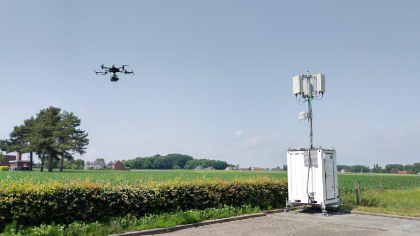
For agricultural, inspection, and mapping drones, the weakest link in the field is rarely the flight controller — it’s the wireless link. Video dropouts, control-command latency, and interference between multiple concurrent aircraft all directly affect operational efficiency and, in some cases, flight safety. Picking the right wireless hardware platform ultimately comes down to trade-offs between throughput, range, integration approach, and deployment environment.

524WiFi and Wallys currently offer three Qualcomm WiFi 7-based platforms that map to different drone video/control link scenarios: DR5322, DR9574S, and DR5424. Here’s how they differ, and which one fits which use case.

DR5322: Lightweight and modular, built for cost-sensitive edge nodes

The DR5322 is built on Qualcomm’s IPQ5322 (quad-core Cortex-A53 @1.5GHz) and is essentially a compact routerboard: onboard 2×2 2.4GHz radio, with 5GHz/6GHz handled through an add-on QCN9274/QCN6274 WiFi 7 module, reaching up to roughly 5764Mbps physical data rate. It offers 4x 2.5G Ethernet ports plus 1x 10G SFP, with 802.3bt PoE support.

This “onboard 2.4G + pluggable high-band module” architecture makes the DR5322 well suited as a relay node or video-transmission hub for a single small multirotor — where the priority is small footprint, low power, and controlled cost rather than maximum throughput. Think field-deployable relay boxes or vehicle-mounted repeaters.

DR9574S: The modular flagship, built for relay towers and multi-drone coordination

The DR9574S runs on Qualcomm’s IPQ9574 (quad-core ARM-A73 @2.2GHz) and is the most configurable of the three — six version options (2×2/4×4, 5G/6G/5-7G) let you tailor the band mix to the project. It supports OFDMA, MU-MIMO, and multi-link operation (MLO), with 10G SFP, 10G Ethernet with PoE, and 2 Gigabit ports, plus optional GPS. Industrial-grade design supports operation from -20°C to 70°C.

This configuration is a better fit for fixed base stations, relay towers, or scenarios that need to manage video/control links for multiple drones at once — for example, a large-scale agricultural operation running several spraying drones simultaneously, where the ground station needs to reliably carry multiple concurrent video and control streams.

DR5424: High-throughput tri-band, built for aggregating high-definition multi-stream video

The DR5424 is the most integrated of the three: Qualcomm IPQ5424 (quad-core Cortex-A55 @1.8GHz), full onboard tri-band WiFi 7 (4×4 MU-MIMO), 320MHz channel width, with theoretical physical data rates up to 1376Mbps on 2.4GHz, 8647Mbps on 5GHz, and 11530Mbps on 6GHz. It also carries the strongest port configuration of the three: 4x 2.5G plus 2x 10G Ethernet.

One important clarification: DR5424’s tri-band design is switchable, not concurrent — the three bands are there to be switched between as needed to avoid interference, not to simultaneously carry separate traffic types (e.g., control on one band, video on another, backhaul on a third). This distinction matters when evaluating a project’s actual concurrent multi-video-stream capacity.

With onboard tri-band radios and multiple high-speed Ethernet ports, the DR5424 is well suited as an aggregation gateway for high-definition, multi-channel video feeds — for example, when several aerial video streams need to be backhauled simultaneously to a ground station for real-time stitching or AI-based analysis.

Side-by-side comparison

DR5322 DR9574S DR5424 Chipset IPQ5322 (A53 @1.5GHz) IPQ9574 (A73 @2.2GHz) IPQ5424 (A55 @1.8GHz) Radio architecture Onboard 2.4G + pluggable 5/6G module Modular, 6 version options (2×2/4×4) Full onboard tri-band, 4×4 Max theoretical rate ~5764Mbps ~5765Mbps (per radio) ~11530Mbps (6GHz) Channel width — Up to 160MHz Up to 320MHz Ethernet 4x 2.5G + 1x 10G SFP 2x 1G + 1x 10G+PoE + 1x 10G SFP 4x 2.5G + 2x 10G GPS No Optional No Typical use case Lightweight relay node / cost-sensitive projects Fixed base station / multi-drone relay tower High-definition multi-stream aggregation gateway

Which one should you choose?

  • Budget-constrained projects that only need to support a single drone or a small number of video links — a lightweight relay node: go with DR5322.
  • Larger operational radius, managing multiple drones online at once, needing a fixed base station or relay tower: go with DR9574S, selecting the version that matches your band requirements.
  • Concurrent high-definition multi-stream video backhaul with high Ethernet aggregation bandwidth requirements, needing an edge gateway: go with DR5424.

All three platforms support OEM/ODM customization, including long-range transmission software tuning, antenna selection, and enclosure design. If you’re evaluating wireless hardware for a drone video/control link project, reach out to info at 524wifi.net or 524wifi.com for selection guidance or to request samples.
Posted on — Leave a comment

How to Design a Reliable Long-Range Wireless Link for Agricultural Drones (WiFi 6/7 Selection Guide)

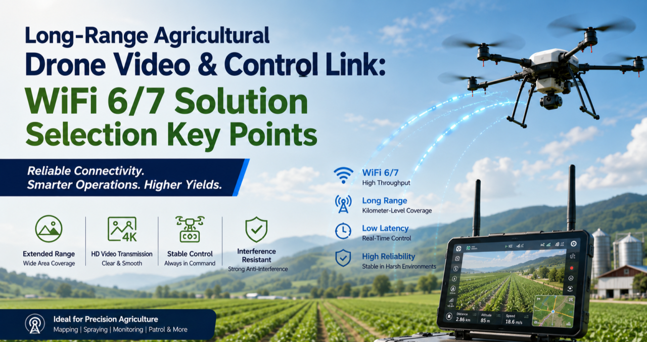
If you’ve deployed drones for crop spraying, field mapping, or orchard inspection over any real distance, you’ve probably run into this: the link holds fine at 200 meters, then starts dropping commands or breaking up video well before you hit the range the datasheet promised. It’s rarely a bad chip. It’s almost always an architecture problem.

This guide walks through why long-range agricultural links behave differently from indoor or short-range WiFi deployments, what actually determines reliability at range, and how to select hardware — control-side and video-side — that holds up in the field.

Why Agricultural Drone Links Are a Different Problem

Most WiFi hardware is designed and benchmarked for indoor, short-range, high-density environments — offices, warehouses, retail. Agricultural drone deployments invert almost every one of those assumptions:

  • Distance is the default, not the exception. A single control link routinely needs to cover several hundred meters to a few kilometers across open farmland or orchards.
  • There’s no multipath to lean on. Indoor WiFi benefits from reflections off walls and ceilings. Open fields don’t offer that — and offer very little shielding from other interference either.
  • Control and video have opposite requirements. Control commands are small, frequent packets that need low, consistent latency and near-zero loss. Video (especially 4K, multispectral, or thermal payloads) needs sustained bandwidth and can tolerate some jitter. Serving both well on one link is hard.
  • One-to-many is common. A single ground station frequently needs to manage multiple aircraft flying formation or covering different zones of the same field, which means the AP side has to handle concurrent, fast-moving clients — not a single static link.
  • Power is capped by regulation, not by ambition. ISM-band transmit power and antenna gain both have legal ceilings. You can’t out-power your way to more range.

The Five Things That Actually Determine Reliability at Range

1. Band Strategy: Split the Link, Don’t Pick One Band

2.4GHz diffracts better around terrain, crops, and structures, which is why it’s traditionally the default choice for long-range control links. 5GHz and 6GHz offer far more spectrum and fewer competing signals, which is exactly what high-resolution video needs.

The reliable pattern in the field isn’t choosing one band for everything — it’s running a split architecture: control on 2.4GHz, video on 5GHz or 6GHz. That’s a strong argument for radio hardware where the band configuration is flexible (single-band, dual-band, or switchable tri-band) rather than fixed to one band at the factory.

2. Modulation and Spatial Streams: Know What They Actually Control

Specs like 4096-QAM and multi-stream MU-MIMO are real and useful — but they define your near-field ceiling, not your far-field floor. As distance increases and signal-to-noise ratio drops, the link automatically falls back to lower-order modulation regardless of the chip’s peak capability.

When evaluating hardware for a long-range deployment, the number that matters isn’t the “Gbps peak” on the datasheet. It’s the rate-adaptation curve under low SNR, and specifically the minimum usable data rate at the outer edge of your intended range. That’s the number that tells you whether video will break up or commands will get dropped when the aircraft is farthest from the ground station — which is exactly when you need the link most.

3. MLO (Multi-Link Operation): Redundancy, Not Traffic Splitting

WiFi 7 introduced Multi-Link Operation, which lets a device establish links across multiple bands or channels at once. There’s a common misconception worth clearing up here: MLO isn’t a way to route control traffic on one band, video on another, and backhaul on a third, each running independently.

What MLO actually does is transmit the same data redundantly across multiple links simultaneously, so that if one link momentarily fades or gets interfered with, the other link covers for it — improving reliability and reducing effective latency. For agricultural drones, where a lost link is often the trigger for a return-to-home failsafe, that kind of redundancy has real operational value, not just a spec-sheet checkbox.

4. Topology: Point-to-Point vs. One-to-Many

A single aircraft doing long-range mapping or inspection is often best served by a point-to-point link — a directional antenna setup trading beamwidth for range and stability. But if a ground station needs to manage multiple aircraft or ground terminals simultaneously, the AP side needs OFDMA multi-user scheduling and fast roaming/handoff behavior, or you’ll see queuing delay whenever multiple aircraft check in around the same time.

Know which problem you’re actually solving before you pick hardware — they call for different radio capabilities.
5. Form Factor: Airborne and Ground-Side Needs Diverge

The airborne side is constrained by payload weight and available power, so it needs a small, low-power radio module that can be integrated directly into a flight controller or gimbal payload — with just enough band flexibility to serve the control link without unnecessary weight or draw.

The ground station side is a different design problem entirely: it needs to aggregate multiple client connections, handle higher sustained throughput, and typically needs wired backhaul (Ethernet, sometimes 10GbE) to move the collected video and telemetry off to a local server or the cloud. That usually points toward a board-level platform rather than a compact module.

Mapping Hardware to the Problem

Once you’ve worked through the five factors above, hardware selection becomes a matter of matching platform to role rather than chasing a single “best” spec sheet.

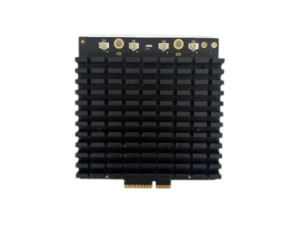
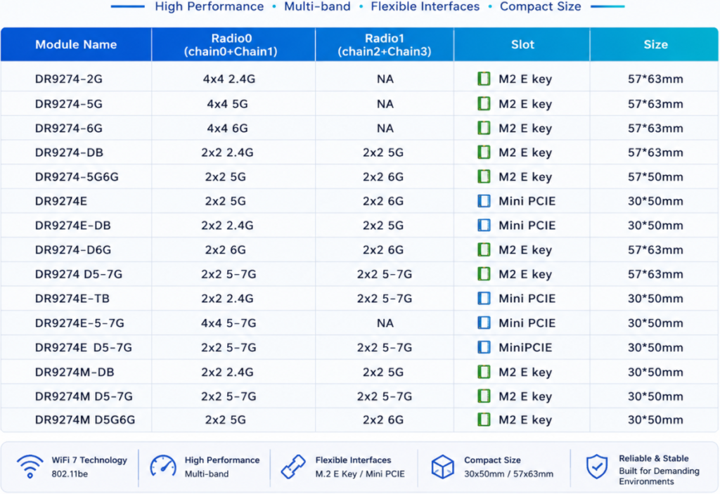
Airborne / terminal-side radio module. You want something small, power-efficient, and configurable — ideally a module where you can select or trim the band configuration (single-band 2.4GHz for a dedicated control radio, or dual-band where the payload allows) without carrying unused radio hardware and power draw. This is the role a WiFi 7 M.2 module built on a chipset like Qualcomm’s QCN9274/QCN6274 platform is designed for, with configurations spanning single-band, dual-band, and 4×4 single-band variants depending on what the airframe needs.
Ground-station aggregation board. This is where you want a flagship-class multi-band platform — four simultaneous bands, wide channels (up to 320MHz), high-order modulation (4096-QAM), multiple M.2 slots for additional radio cards, and dual 10GbE-class wired uplinks. This tier handles concurrent multi-aircraft connections, dynamic channel selection (AFC) to work around interference, and reliably backhauling the aggregated video streams to wherever they’re processed.
Edge gateway with onboard compute. For deployments where you want to do video processing or stream aggregation closer to the field — rather than pushing everything raw to the cloud — a tri-band gateway platform with high-speed wired I/O (dual 10GbE + multiple 2.5GbE) and an onboard AI accelerator tuned for networking workloads is the better fit. It handles wireless backhaul while also doing local compute, cutting the bandwidth pressure on the uplink.

A Practical Decision Order

When you’re actually speccing a system, work through it in this order:

  1. Point-to-point or one-to-many? This determines whether OFDMA and fast roaming on the ground-station side are must-haves or nice-to-haves.
  2. Does the control link need to be physically separated from the video link? This determines whether a single-band module or a multi-band board is the right call for each end of the system.
  3. What are the payload’s power and space constraints? This determines module-level vs. board-level hardware on the airborne side.
  4. Does the back end need edge compute or multi-stream video aggregation? If yes, prioritize a gateway platform with onboard AI acceleration and high-speed wired I/O.

FAQ

Is 2.4GHz or 5GHz better for a long-range drone control link? 2.4GHz generally holds up better over distance and around obstructions like terrain or crop canopy, which is why it’s the more common choice for the control link specifically. 5GHz and 6GHz are typically reserved for the video link, where the extra bandwidth matters more than raw range.

Do I need WiFi 7, or is WiFi 6 enough? It depends on whether you need MLO’s link redundancy and whether your video payload actually needs the extra bandwidth WiFi 7’s wider channels provide. Many long-range control links work fine on WiFi 6; WiFi 7 becomes more valuable as video resolution, aircraft count, or reliability requirements increase.

What’s the actual benefit of MLO for a drone link? Redundancy. The same data is sent across multiple links at once, so a momentary fade on one link doesn’t cost you the connection — it isn’t a way to assign different traffic types to different bands independently.

Should the airborne radio and the ground-station radio be the same hardware? No — they’re solving different problems. The airborne side prioritizes size, weight, and power; the ground station prioritizes aggregate throughput, multi-client handling, and wired backhaul capacity.


If you’re evaluating or redesigning the wireless subsystem in a drone flight-control or video-transmission stack — or migrating an existing deployment from WiFi 5/6 to WiFi 7 — reach out to info at 524wifi.com or .net. We build radio hardware across all three tiers described above and can walk through the specifics of your deployment.

Posted on

QCA9880 to QCN9274/QCN6274: A WiFi 5 to WiFi 7 Module Selection Guide — 524WiFi 600VX / 900VX and DR9274E-TB Compared

From QCA9880 to QCN9274/QCN6274: A WiFi 5-to-WiFi 7 Module Selection Guide — 524WiFi 600VX / 900VX, and DR9274E-TB Compared

For years, the Qualcomm-Atheros QCA9880 has been the default chipset behind a lot of industrial WiFi 5 designs — routers, CPEs, access points, embedded gateways. It’s mature, well-documented, and easy to source, which is exactly why so many product lines are still built around it. But the ground is shifting. As more networks have to handle a pile of devices talking at once — robot fleets on a warehouse floor, banks of industrial cameras, multiple video streams heading back to a controller — WiFi 5’s two crowded bands start to show their age, and WiFi 7 platforms have gotten mature enough to be a real option instead of just a roadmap item.

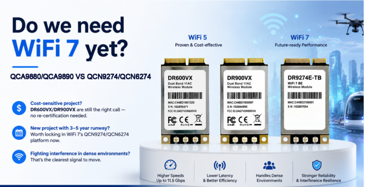
We get this question a lot from customers still speccing hardware around QCA9880: is it time to move, and if so, to what? Below is a practical comparison of two of our QCA9880 modules, 524WiFi 600VX / 900VX Pro+, against DR9274E-TB, which runs on Qualcomm’s newer QCN9274/QCN6274 platform.

The three modules

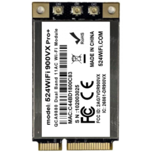
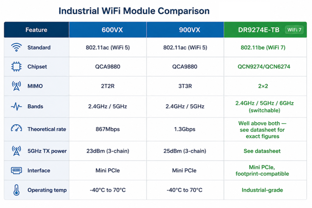
524WiFi 600VX Pro+ and DR600VX are a 2×2 MIMO 802.11ac module — 2T2R, theoretical throughput up to 867Mbps. Two UF.L antenna connectors, 2.4GHz and 5GHz (including 4.9GHz), TX power up to 24dBm/23dBm, Mini PCIe interface, -40°C to 70°C operating range. It’s a small board — 30.0 × 50.9 × 3.2mm — and it’s been a workhorse for cost-sensitive designs that don’t need a third antenna chain.

524WiFi 600VX Pro+ and DR600vx – QCA9880 2X2

524WiFi 600VX Pro+ and DR900VX are the same chipset, same footprint, same pinout — but 3×3 MIMO instead of 2×2, pushing theoretical throughput to 1.3Gbps and TX power up a couple of dB (26dBm/25dBm) thanks to the extra chain. There’s also a DR900VX-i variant on QCA9890 rated for 85°C, and a DR900VX-4.9 with 4.9GHz support. Because the mechanical and electrical interface is identical to DR600VX, swapping between the two mostly comes down to whether your enclosure has room to route a third antenna.

524WiFi 900VX Pro+ and DR900vx – QCA9890 3X3

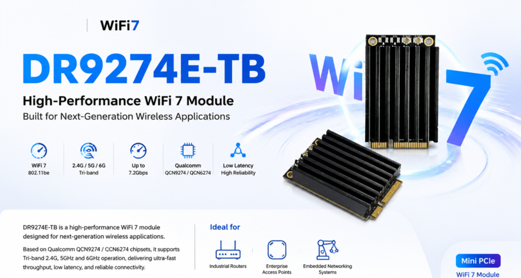
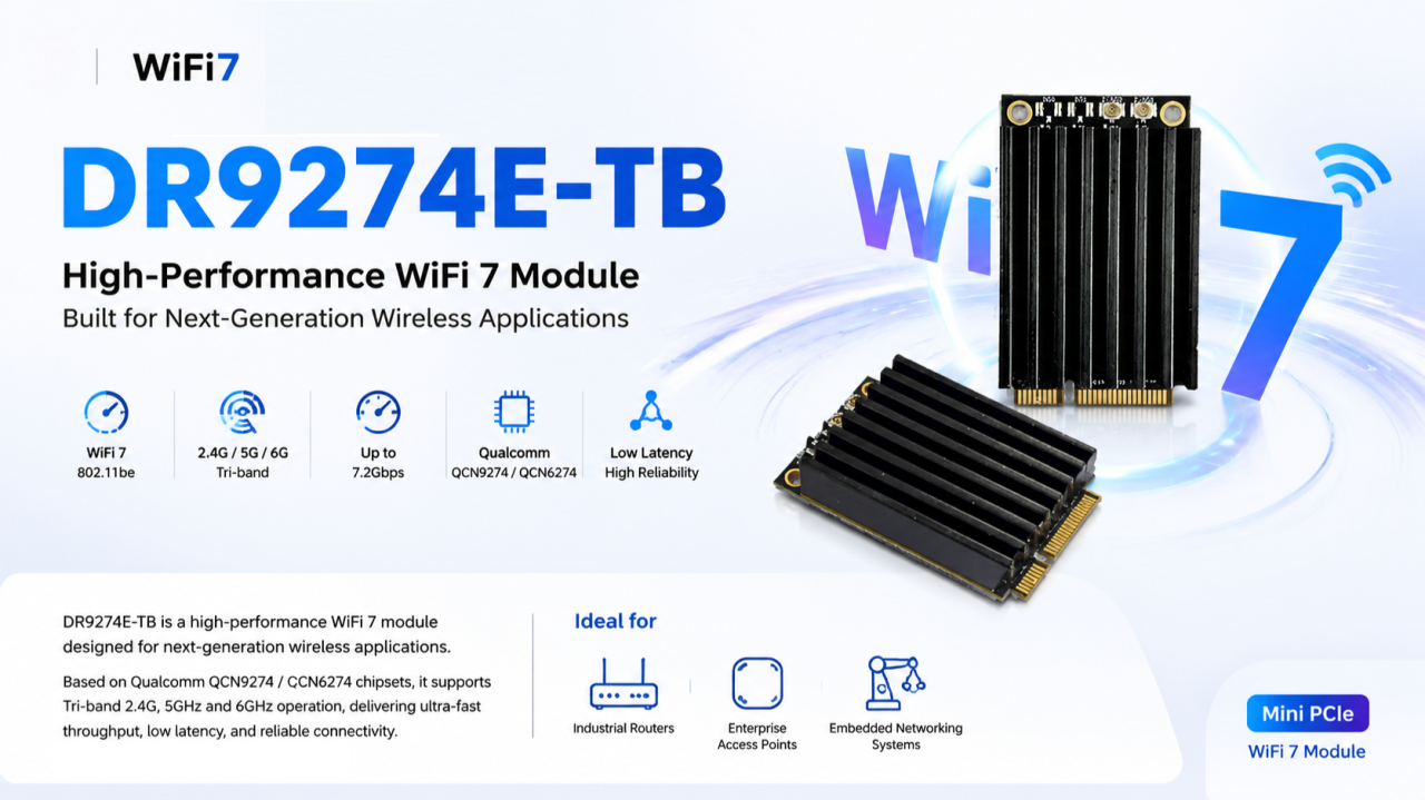
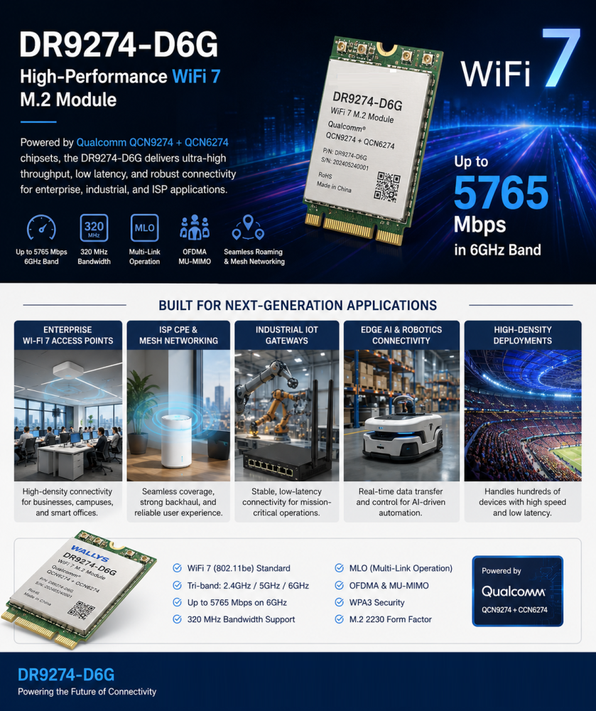
DR9274E-TB is a different generation entirely. It’s built on QCN9274/QCN6274 and supports WiFi 7 (802.11be) across three bands — 2.4GHz, 5GHz, and 6GHz. Worth being precise here: it’s tri-band switchable, meaning the module picks the best band to operate on, not three bands running separate traffic simultaneously. It’s a 2×2 MIMO design, Mini PCIe, and mechanically compatible with existing WiFi 5 module footprints, so it’s aimed at the same kinds of products — industrial routers, enterprise APs, outdoor CPEs and bridges, mesh systems, edge AI platforms — just with more headroom.

Side by side

QCA9880 VS QCN9274

What actually changes

Going from 2T2R to 3T3R (600VX to 900VX) is a fairly straightforward upgrade — one more spatial stream, a bit more throughput, and a bit more stability in multipath environments, since the extra chain gives the radio more to work with. If your enclosure has the space and the budget allows it, 524WiFi 900VX Pro+ is the easy call.

The jump to WiFi 7 is a different kind of change, and it’s not really about raw speed. The number that matters most is 6GHz — an almost entirely clean band with none of the legacy congestion that 2.4GHz and 5GHz have accumulated over a decade of deployments. In a warehouse or factory environment with dozens of APs and client devices fighting for airtime, that alone can matter more than any Mbps figure on a spec sheet. WiFi 7 also brings multi-link operation, which lets a device coordinate traffic across bands rather than being locked to one — though how much of that you actually get depends on chipset support and firmware, so it’s worth checking specifics for your use case rather than assuming every feature is turned on out of the box.

None of this means everyone needs WiFi 7 today. A lot of deployments — point-to-point links, smaller networks, applications without dozens of devices packed into one space — are still perfectly well served by QCA9880. The cases where it’s worth moving now are the ones already running into interference or density problems, or new designs with a long enough runway that the 6GHz advantage will keep paying off for years.

Which one fits your project

If you’ve already built a product around QCA9880 — PCB layout done, drivers sorted, certifications in hand — there’s usually no reason to change anything. 524WiFi 600VX Pro+ and 524WiFi 900VX Pro+ share a footprint and pinout, so you can pick between them based on cost and available antenna space without touching your certification.

If you’re starting a new design with a multi-year lifecycle ahead of it, DR9274E-TB is worth a serious look even though WiFi 7 silicon costs more up front. QCA9880 is an older chipset generation at this point, and long-term sourcing risk tends to creep up as a platform ages. Locking in 6GHz early also means you’re not scrambling to redesign in a couple of years when everyone else has already made the jump.

And if you’re already seeing throughput drop off or latency get jittery once you cross a certain device count — a common story with AMR fleets, multi-camera vision setups, dense AP coverage — that’s usually a clearer signal than any roadmap discussion. Tri-band switching, combined with sensible planning around which traffic goes where, tends to ease that bottleneck in a way a WiFi 5 dual-band design just can’t.

Bottom line

  • Sticking with an existing QCA9880 design, watching cost closely → 524WiFi 600VX or 524WiFi 900VX Pro+
  • New project, long lifecycle, want to be ahead of the spectrum curve → DR9274E-TB
  • Already fighting interference or density issues → DR9274E-TB

Every deployment is a little different, and the right call depends on your device density, antenna space, budget, and how long the product needs to stay in the field. If you want to talk through your specific case, or need test data, samples, or custom development — antenna layout, firmware tuning, OEM/ODM support — reach out info at 524wifi.net .

Posted on

Why Your Next Edge AI Platform Needs a Tri-Band WiFi 7 Module, Not Just Dual-Band

Wireless is usually the last spec finalized on an edge AI hardware design and the first thing that becomes a bottleneck in the field. Worth a closer technical look before your next carrier board revision locks in.

The RF problem, precisely

Dual-band designs (2.4GHz + 5GHz) share spectrum with every consumer device, AP, and IoT sensor in range. In dense deployments — multi-robot fleets, factory floors, warehouses — this shows up as elevated retransmission rates, unpredictable jitter, and tail latency spikes under contention. For a control loop or a real-time inference pipeline streaming sensor data upstream, tail latency is what actually breaks the system, not average throughput.

WiFi 7 (802.11be) addresses this at the PHY/MAC level in three ways relevant to edge AI hardware:

  • 6GHz band access — largely unlicensed spectrum with far lower device density than 2.4/5GHz today, meaning lower channel contention and more predictable airtime
  • 320MHz channel bandwidth (vs. 160MHz max on WiFi 6) — higher raw throughput ceiling per link
  • Multi-Link Operation (MLO) — the ability to aggregate or fail over across bands simultaneously, so a device isn’t fully dependent on the health of a single channel

For an edge AI box pushing multi-camera streams, sensor fusion data, and periodic model/OTA updates concurrently, MLO plus 6GHz access is the difference between throughput that holds up under real RF load and throughput that only looks good on an open-air bench test.

Module-level implementation: DR9274E-TB

We built the DR9274E-TB around this exact requirement — a Mini PCIe WiFi 7 module for teams integrating wireless into embedded and industrial platforms rather than designing RF from scratch.

Specs:

  • Chipset: Qualcomm QCN9274 (5G/6G radio) + QCN6274 (2.4GHz radio) — Qualcomm’s WiFi 7 platform, not a rebadged WiFi 6E part
  • Band support: Tri-band, 2.4GHz / 5GHz / 6GHz
  • Antenna config: 2×2 MIMO
  • Interface: Mini PCIe — integrates without a carrier board redesign on most existing embedded platforms
  • OS support: Linux-compatible — relevant if your stack runs on JetPack, Yocto, or a custom embedded distro
  • Build: Industrial-grade components rated for continuous operation, not consumer-grade parts pushed into an industrial enclosure

Where the tri-band architecture actually matters

Not every application needs 6GHz. It matters specifically where you have:

  • High device density (multi-robot fleets, dense AP deployments)
  • Latency-sensitive control or telemetry loops
  • Concurrent high-bandwidth streams (multi-camera vision, sensor fusion payloads)
  • Environments where 2.4/5GHz spectrum is already saturated by other systems

That covers most edge AI computing platforms, industrial routers/IoT gateways, enterprise APs in high-density environments, outdoor CPE/wireless bridges, and mesh networking nodes.

The engineering takeaway

Specifying wireless the way you did for a WiFi 5/6 design — pick a dual-band module, move on — leaves latency and reliability headroom on the table that your compute stack has already outgrown. Tri-band WiFi 7 with MLO isn’t a marketing checkbox; it’s a direct answer to the contention and jitter problems that show up specifically under production RF conditions, not lab conditions.

Happy to go deeper on channel planning, MLO configuration, or driver-level integration for teams currently specifying wireless for a Jetson-based or other edge AI carrier board.

📩 Reach out to 524WiFi for datasheets, samples, or OEM customization.

Posted on

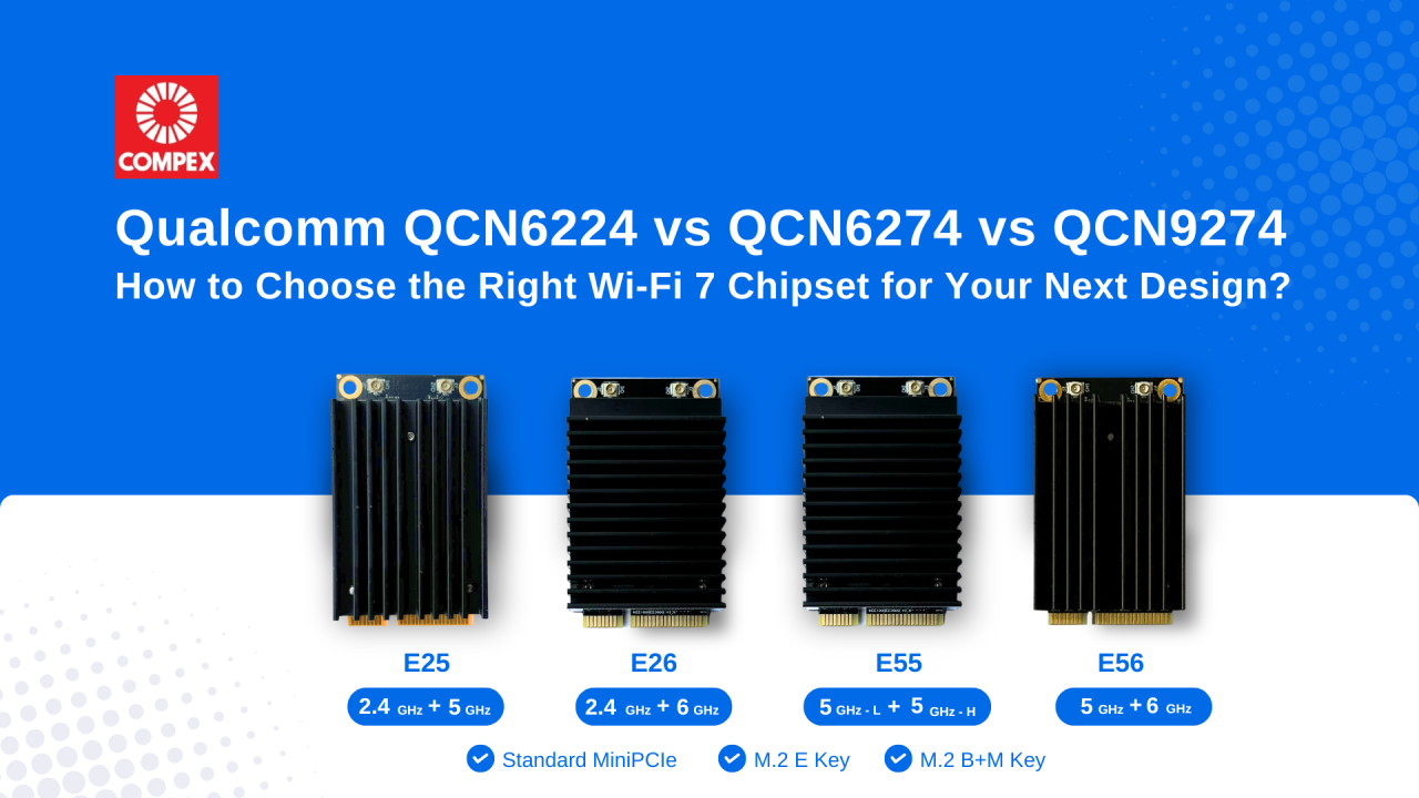
Qualcomm QCN6224 vs QCN6274 vs QCN9274: Which Wi-Fi 7 Chipset Should You Design With?

Wi-Fi 7 is rapidly becoming the standard for enterprise networking, industrial IoT, Edge AI and next-generation wireless infrastructure. When choosing between Qualcomm’s QCN6224, QCN6274, and QCN9274, engineering teams often ask us which one is “best.” The real question is: Which one fits your application’s capacity, thermal and cost?

Here is a quick breakdown to guide your next design:

Qualcomm QCN6224

It is designed for applications where cost efficiency and reliable Wi-Fi 7 performance are priorities, well suited for embedded systems and entry-level enterprise networking products. Supporting up to 128 concurrent clients, it offers reliable wireless performance for applications that do not require extremely high connection density. For many OEMs/ ODMs, QCN6224 offers an excellent balance between performance and affordability.

Qualcomm QCN6274

The Qualcomm QCN6274 targets enterprise-class networking. With support for the 6 GHz spectrum, wider channel bandwidth and up to 256 clients, it is well suited for enterprise access points, smart manufacturing, healthcare and campus networks where higher capacity is required.

Qualcomm QCN9274

The Qualcomm QCN9274 is Qualcomm’s flagship Wi-Fi 7 networking chipset for demanding enterprise and industrial applications. Supporting up to 512 concurrent clients, it is ideal for high-density enterprise deployments, mission-critical wireless infrastructure and industrial applications that demand maximum wireless capacity and low latency.

Article content
ChipsetNo of ClientsBest ForKey Advantages
QCN6224Up to 128 clientsSmall-Medium Business NetworkingCost-effective Wi-Fi 7 performance
QCN6274Up to 256 clientsEnterprise Access PointsHigher throughput, 6 GHz support, enterprise scalability
QCN9274Up to 512 clientsHigh-density Enterprise, Mission-critical NetworksMaximum capacity, advanced RF performance, premium enterprise features

Rather than asking which chipset is “better,” a more important question is: Which chipset is the right fit for your application requirements?

Choose Qualcomm QCN6224 when cost efficiency and dependable Wi-Fi 7 performance are your priorities.

Choose Qualcomm QCN6274 when your product needs higher throughput, 6 GHz support and greater client capacity.

Choose Qualcomm QCN9274 when you are designing high-density wireless infrastructure where scalability, low latency and high concurrent client capacity are critical.

Looking Beyond the Chipset

Selecting the right chipset is only one part of developing a successful Wi-Fi 7 product. RF front-end design, thermal dissipation and host platform integration can add months to your development cycle.

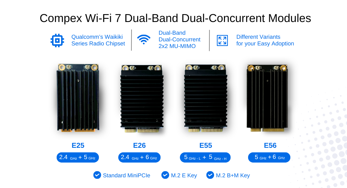
At 524WiFi and Compex, our Wi-Fi 7 Module Family supports single and dual-band configuration with both commercial grade and industrial grade chipset. Available in standard MiniPCIe form factor and M.2 variants, the module family are compatible with Qualcomm platforms as well as various third-party industrial CPU platforms, including Intel x86, NVIDIA and ARM-based processors such as NXP and Marvell, helping OEMs/ ODMs reduce integration risk and accelerate product development.

To learn more about Compex Wi-Fi 7 Standard MiniPCIe and M.2 Qualcomm-based Wi-Fi 7 module, contact us directly !

Posted on

GPS Smart Deployment for Long-Range WiFi PtP: What If Your AP Could Tell You Where to Point?

Deploying long-range wireless links has always been a field engineering challenge.

For a Point-to-Point (PtP) wireless connection, performance depends heavily on antenna alignment.

A few degrees of misalignment can mean:

  • Lower throughput
  • Reduced link stability
  • Poor signal quality
  • More time spent on-site troubleshooting

Traditionally, engineers need to rely on:

  • GPS devices
  • Maps
  • Compass tools
  • Signal strength monitoring
  • Multiple technicians communicating between two locations

But what if the wireless device itself could help you find the right direction?


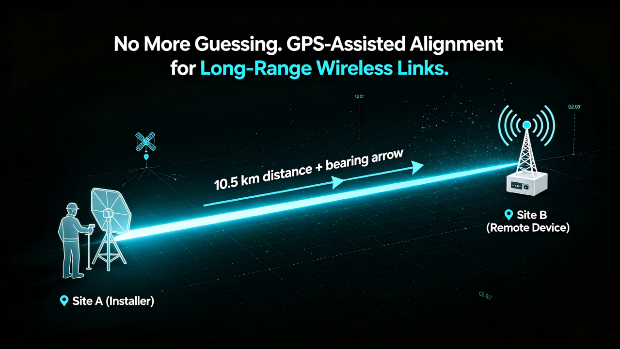
From GPS Location to Smart Alignment

Imagine this:

You install an AP at the local site.

After powering it on:

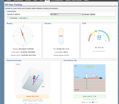
  1. The device automatically obtains its GPS coordinates.
  2. The remote site device shares its location information.
  3. The web interface calculates the optimal alignment direction.
  4. The system provides recommended:
  • Horizontal rotation angle (Azimuth)
  • Vertical tilt angle (Elevation)

Instead of asking:

“Which direction should I point this antenna?”

The system tells you:

“Rotate 127.5° horizontally and tilt 8.3° upward.”


Simplifying Long-Distance Wireless Deployment

For outdoor wireless networks, especially:

  • WISP networks
  • Rural broadband
  • Industrial campuses
  • Mining sites
  • Smart agriculture
  • Remote monitoring systems

deployment efficiency is critical.

GPS-assisted alignment can help engineers:

✅ Reduce installation time

✅ Minimize alignment errors

✅ Improve first-time connection success rate

✅ Simplify remote deployment and maintenance


How It Works

A GPS-enabled wireless platform combines:

1. Location Awareness

Each device knows its own:

  • Latitude
  • Longitude
  • Position information

2. Remote Device Coordination

The AP exchanges location data with the remote endpoint.

3. Direction Calculation

Based on two GPS points, the system calculates:

  • Distance between sites
  • Direction angle
  • Antenna pointing recommendation

4. Web-Based Guidance

Engineers can view the recommended installation angle directly through the device management interface.

Article content

No additional measurement tools required.


Designed for Next-Generation Outdoor Connectivity

524WiFi and Wallys have integrated GPS capability into selected industrial wireless platforms, including:

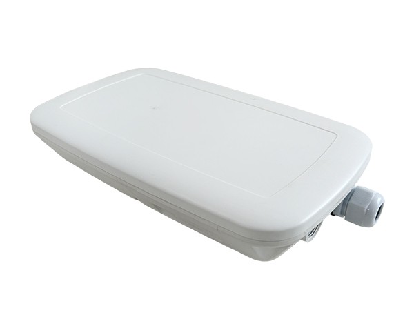
524WiFI WiFi 6 Long Range Kit

DRWAVE-1000 Built around Qualcomm IPQ5018 platform, designed for industrial networking applications requiring reliable wireless connectivity.

Article content

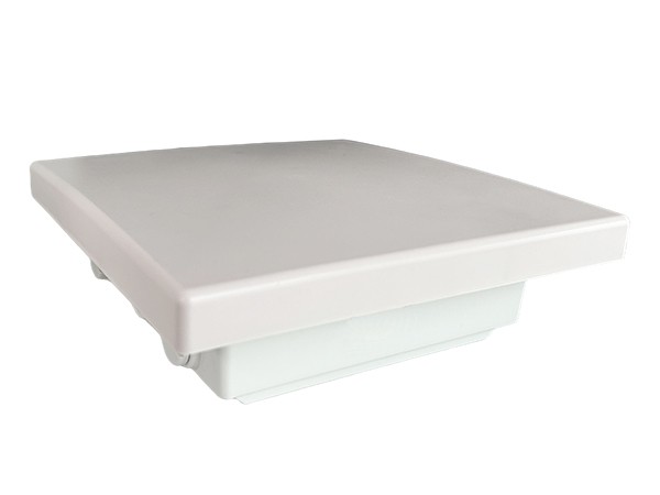
524WiFi WiFi 7 Long Range Kit

Powered by Qualcomm IPQ9574, supporting next-generation high-performance wireless applications.

Article content

With GPS integration, these platforms enable smarter deployment possibilities for long-range wireless networks.

Posted on

5G SA / NSA vs 4G LTE Coverage and technology

5One common assumption we encounter is that moving from 4G LTE to 5G will automatically improve network coverage. After all, newer technology should be better… right? The reality is a bit more complicated – again and again.

For many IoT applications, coverage is determined far more by frequency than by the generation of cellular technology itself. An LTE device operating on low-band can often outperform a 5G device using mid-band when it comes to indoor penetration and reach into challenging environments such as basements and utility cabinets.

Part of the early promise of 5G was that technologies such as Dynamic Spectrum Sharing (DSS) would allow operators to introduce 5G while leveraging the coverage footprint already established by LTE. While DSS certainly accelerated early deployments, many operators are now evolving their strategies as networks mature, balancing capacity, efficiency, and spectrum utilization to meet growing demand (https://www.lightreading.com/5g/the-quiet-sunset-of-5g-dynamic-spectrum-sharing).

Then there’s another point: 5G Standalone (SA) vs Non-Standalone (NSA). Most of today’s 5G deployments are still NSA, meaning they continue to rely on the existing LTE core network for signalling and control. True 5G SA deployments offer the full promise of 5G with network slicing and super low latency being key factors, but they remain relatively uncommon. Or, to put it another way: 5G Standalone deployments are quite (stand)alonely!

You also have the “LPWA is 5G” proponents but we’re talking real 5G here. So what’s the takeaway? The “best” cellular technology isn’t necessarily the newest one; the right choice depends on what you’re trying to achieve.

If your application requires high throughput, low latency, or is designed with future 5G capabilities in mind, then 5G may well be the obvious choice for you. On the other hand, if your priorities are coverage in difficult environments, low power consumption and/or cost control, LTE technologies still make a very compelling case. The good news? We really love this stuff.

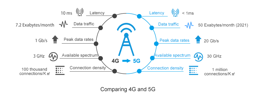
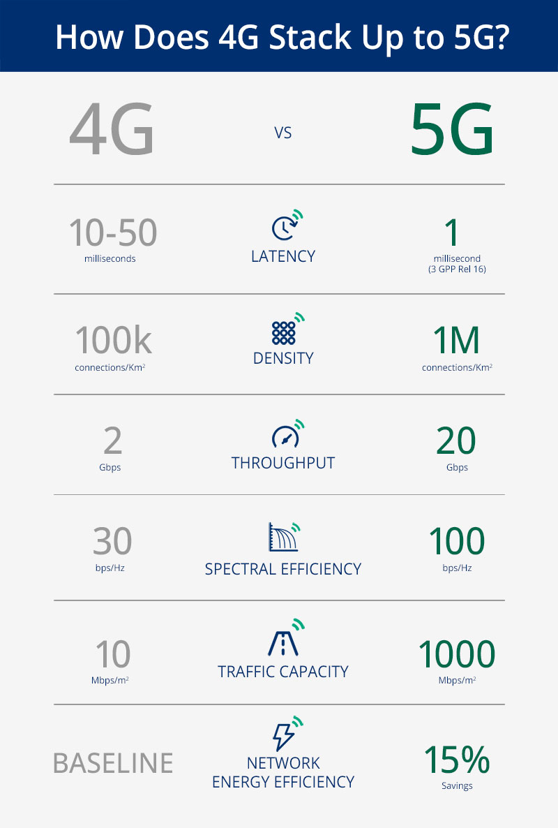
4G Vs. 5G Key Technology Differences

Choosing the right cellular technology isn’t always straightforward, but that’s where we can help. Whether you’re evaluating LPWA, LTE, or NR, we’d be happy to discuss your application, and help you navigate the intricacies of module selection to find the best fit for your project.

In this article, I will address and review the Key technology differences between 4G and 5G; reading this topic is crucial, especially if you have a good background in 4G and have just started your 5G Career.

This article will cover the differences between 4G & 5G for the following

No alt text provided for this image
Content

RAN Structure: 4G, 5G NSA & 5G SA

From the Radio Access Network side, The overall structure looks very similar, for example;

  • X2 interface connecting different 4G Nodes was replaced by the Xn interface
  • S1 interface connecting BTS Side to the Core network replaced by Ng interface
  • MME replaced by AMF and SGW replaced by UPF

From a superficial view, it is a matter of naming change; however, there are subtle changes implemented that leads to huge improvement; we will be addressing one of the points which can lead to improving latency in 5G SA.

No alt text provided for this image
RAN Structure

One of the main differences provided in 5G SA Architecture is that the User plane and Control function has separated; see below comments and the 4G & 5G Full Architecture for more details.

  1. An important Characteristic of the 5G System is separating the user plane and control plane functions, which differs from the original 4G System architecture in the following:

In 4G: P-GW provides both control plane and user plane functions(IP Address allocation & Packet Forwarding)

In 5G: SMF Provides IP Allocation, and UPF provides packet forwarding

2. User and Control plane separation allows independent scaling of the two functions

Operators can add more user plane capabilities without having to add more control plane

Minimize latency by distributing User plane and keeping it geographically close to the AN

Packet Gateway provides both User plane and Control Plane function in 4G

No alt text provided for this image
4G Architecture

While in 5G, Only UPF provides User plane function.

No alt text provided for this image
5G Architecture: Pictures captured from 5G NR in Bullets

Quality of Service: 4G & 5G

For the QoS Part, there is an essential change in the way of how the QoS is being allocated.

In 4G, EPS Bearer is responsible for providing E2E User Plane connectivity between the UE and Access Point Name “APN” within the Packet Gateway

*APN defines the interface to the external data network

The point here is that EPS Bearer has a one-to-one mapping to the QoS, This means that the User needs to establish a new EPS bearer every time there is a new QCI assignment, Only One QoS(Example QCI 9 can be assigned to one DRB) with no flexibility.

No alt text provided for this image
4G QoS

In 5G, PDU Sessions is responsible for providing E2E User Plane connectivity between the UE and Data Network Name “DNN” within the User Plane Function ( UPF)

*DNN defines the interface to the external data network

However, Unlike 4G EPS Bearer, PDU Session supports one or more QoS Flows, Which means that QoS Flow to radio bearer mapping is not necessarily one-to-one mapping and multiple QoS can be mapped to the same Radio Bearer.

No alt text provided for this image
5G QoS

Note: QoS Flows belonging to different PDU Sessions are mapped onto different DRBs.


Radio Protocol Stack: 4G & 5G

SDAP Primary Task:

Service Data Application Protocol (SDAP) is responsible for mapping QoS bearers to radio bearers according to their quality-of-service requirements. This protocol layer is not present in LTE but introduced in NR when connecting to the 5G core network due to the new quality-of-service handling

The new SDAP (Service Data Adaptation Protocol) primary function maps each QoS Flow onto a specific Data Radio Bearer

•Multiple QoS Flows can be mapped onto a single DRB or,

•Single QoS Flow can be mapped onto a single DRB.

No alt text provided for this image
Radio Protocol Stack: SDAP Layer added in User-Plane
No alt text provided for this image
SDAP Layer

Overall Technology Comparison

No alt text provided for this image

4G Vs. 5G Bandwidth

4G Supports a maximum up to 20Mhz BW, While 5G is up to 400Mhz

5G offers less Guard Band(2~5) and Higher Spectrum Utilization(Utilizing up to 95% of the Channel BW, While 4G Utilize 90%)

Up to 20x Higher Bandwidth and New Spectrum Definition. (ex. mmwave)

NR Offers Less Guard-band and Higher spectrum utilization

No alt text provided for this image
*Source: 3GPP TS 38.101 & TS38.104

Frame Structure Comparison: 4G & 5G

The following summarized the main differences between 4G & 5G Frame Structure

  1. Frame and Subframe duration remained the Same for 5G
  2. Number of Symbols in a slot is now fixed to 14 in 5G (4G is fixed to 7)
  3. 5G has a flexible numerology, which allows different configurations as the Slot Duration relies on SCS(Sduration = 1 /SCS)
  4. 5G is now using a Slot as a scheduling Unit instead of Sub-frame compared to 4G
  5. NR RB Resource Grid is double 4G(14 vs. 7 OFDM symbols in one RB )
No alt text provided for this image

Physical Channel & Signals Comparison : 4G & 5G

The below table summarizes the main differences in Physical Channel and Signals

No alt text provided for this image

Downlink Comparison: Physical Downlink Control Channel(PDCCH)

  • In LTE, PDCCH control channels are always distributed across the entire system bandwidth.
  • NR PDCCHs are designed to transmit in a configurable control resource set (Called CORESET).
No alt text provided for this image

Uplink Comparison: Physical Uplink Control Channel(PUCCH)

In 4G, PUCCH is transmitted in one or more Physical Resource Blocks (PRB) at the edges of the system bandwidth and is only supporting Long-Format(duration 1 ms)

No alt text provided for this image

While 5G supports both Long and short format, Where short format provides the following:

  • 1~2 Symbols over the complete
  • Provides Better Latency
No alt text provided for this image

PBCH & Synchronization Signals: 4G & 5G

There are 2 main changes in PBCH and SS compared to 4G:

PBCH and SS are now being combined into SSB

SSB Frequency domain location is flexible and can be configured at different locations based on the network requirements(4G PBCH & SS are fixed at the center of Channel BW)

No alt text provided for this image

Broadcast Channel Comparison: 4G & 5G

4G Provide Wide Beam coverage, while 5G provides narrow beam coverage for broadcast channels, which can improve the Coverage and Quality

No alt text provided for this image

Reference Signal Overhead comparison: 4G & 5G

5G Overhead is almost half 4G, and the mean reason behind that 5G has no Cell Specific Reference Signal as 4G

As you know that CRS was all the time transmitted “Always on” over the entire BW and consume a large number of resource elements within the Resource block

While 5G uses DMRS for channel demodulation instead of CRS.

PDSCH DMRS offers much less overhead compared to CRS due to the following:

DMRS is transmitted within the set of RBs allocated to PDSCH. i.e, if a UE is allocated 10RBs for PDSCH, then both PDSCH and DMRS will be transmitted across those BW

DMRS Configuration type 1 uses 6 RS within one or two symbols, which add around 3.6% up to 7% overhead to 5G, while 4G offers from 9% to 17% overhead. Please see the below picture for more details and refer to the below-attached video for more information.

No alt text provided for this image


Key differences in Link Budgets: 4G & 5G

4G & 5G almost have the same Link Budget Basic Methodology

Link Budget is counting all of the gains and losses from the TX through the medium(Free Space, Cables, etc.) to the receiver

Simple Link Budget Equation:

•Received Power(dBm) = TX Power(dBm) + Gains – Losses

No alt text provided for this image

Main consideration:

No alt text provided for this image

Materials uploaded to below blog

Posted on

When Robots Move Beyond Wi-Fi Coverage: Why Mesh Matters

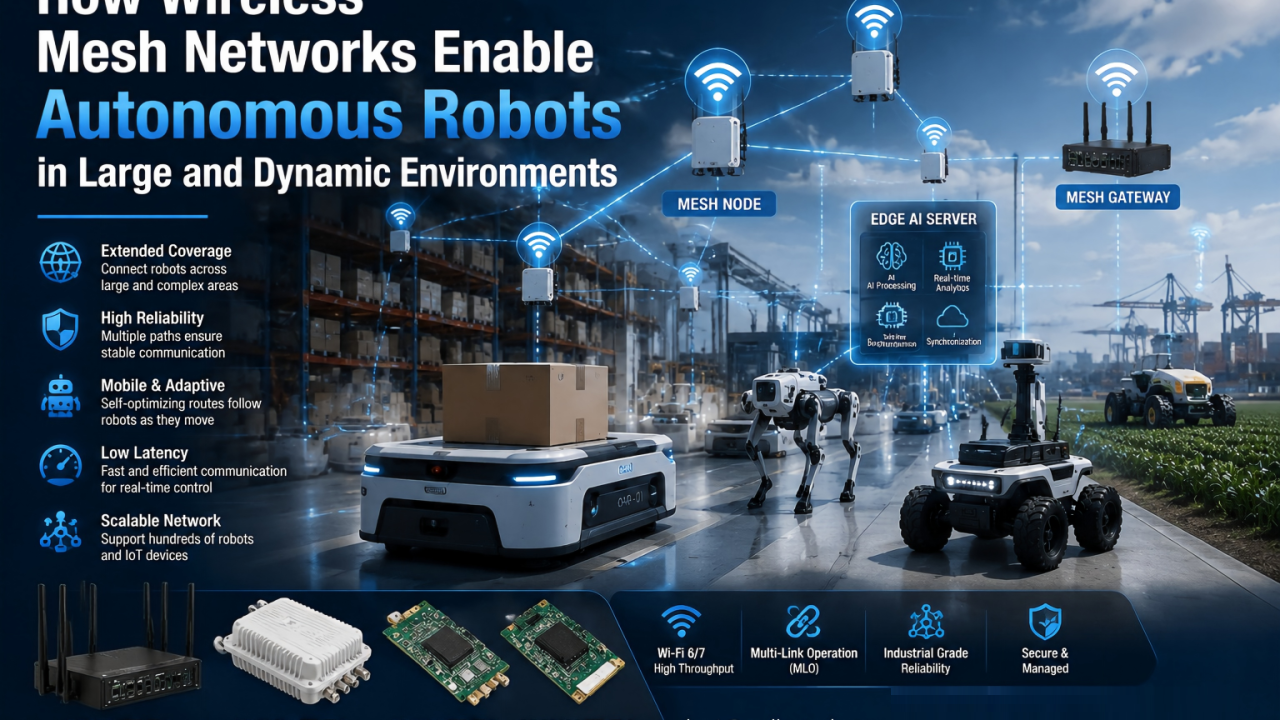
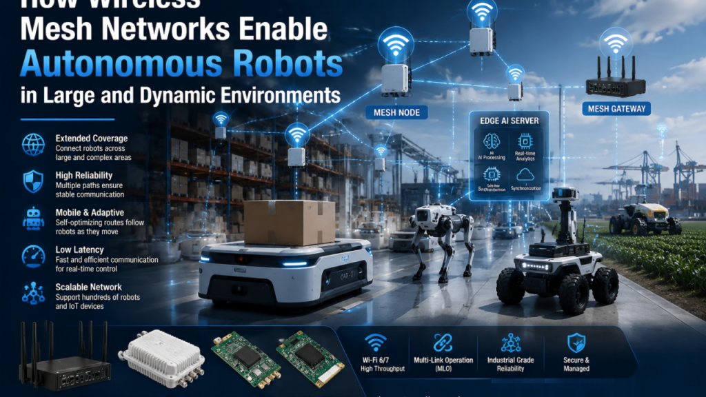
How Wireless Mesh Networks Enable Autonomous Robots in Large and Dynamic Environments

The future of robotics is moving beyond controlled spaces.

Autonomous robots are no longer limited to laboratory demonstrations or small indoor environments.

Today, robots are being deployed in:

  • Large warehouses
  • Smart factories
  • Outdoor farms
  • Ports and logistics centers
  • Mining sites
  • Industrial inspection areas
  • Hospitals and commercial buildings

As robot deployment expands, one challenge becomes increasingly important:

How do we maintain reliable connectivity when robots move beyond traditional Wi-Fi coverage?

The answer is not simply adding more access points.

The future of autonomous robotics requires a more flexible and intelligent wireless infrastructure.

This is where wireless mesh networking becomes increasingly important.


Autonomous Robots Need Connectivity Everywhere They Operate

A robot is only autonomous when it can continuously:

  • Sense its environment
  • Process information
  • Communicate with other systems
  • Receive updates
  • Report status

Connectivity enables critical robot functions:

  • Navigation assistance
  • Remote monitoring
  • Fleet management
  • Mission updates
  • Data synchronization
  • Safety communication

For a fixed device, losing wireless connectivity may be inconvenient.

For an autonomous robot, connectivity loss can impact the entire operation.

A warehouse robot that loses connection may stop.

An inspection robot that disconnects may fail to complete a mission.

A farming robot operating in a large field may become unreachable.

Reliable wireless communication is not an optional feature.

It is operational infrastructure.


The Limitation of Traditional Wi-Fi Networks

Traditional Wi-Fi deployments are usually designed around fixed infrastructure:

Access Point → Client Device

This works well for:

  • Offices
  • Small factories
  • Indoor environments

However, robotics introduces new challenges.

1. Large Operating Areas

Many robotic applications cover large spaces:

  • Warehouses with thousands of square meters
  • Outdoor industrial sites
  • Agricultural fields
  • Logistics yards

Installing wired access points everywhere may become:

  • Expensive
  • Difficult to maintain
  • Limited by infrastructure availability

2. Dynamic Robot Movement

Robots are constantly moving.

Their communication environment changes every second.

A robot may travel:

  • From one building to another
  • Through different production areas
  • Around obstacles and machinery

The wireless network must adapt dynamically.


3. Rapid Deployment Requirements

Many robotics deployments need flexibility.

For example:

A logistics company may expand warehouse operations.

A factory may redesign production lines.

An agricultural operation may deploy robots across changing areas.

A wireless solution should not require rebuilding the entire network every time the environment changes.


What Is Wireless Mesh Networking?

A traditional Wi-Fi network depends mainly on wired access points connected to a central network.

A wireless mesh network creates multiple communication paths.

Instead of:

Robot → Access Point → Network

A mesh environment can support:

Robot → Robot → Mesh Node → Network

or:

Robot → Mesh Node → Mesh Node → Gateway

Each node can help extend network coverage and improve flexibility.


Why Mesh Matters for Autonomous Robots

1. Extending Coverage Across Large Areas

Robots often operate in places where complete wired infrastructure is difficult.

Examples:

Smart Agriculture

Autonomous agricultural robots may operate across:

  • Fields
  • Orchards
  • Greenhouses

Mesh networking can help extend connectivity across larger areas without requiring extensive cabling.


Industrial Sites

Factories and industrial facilities often include:

  • Metal structures
  • Moving equipment
  • Complex layouts

Mesh networks can provide more flexible coverage.


Warehouses

Large warehouses may contain:

  • High shelves
  • Multiple zones
  • Moving inventory systems

A flexible wireless architecture helps robots maintain communication while navigating different areas.


2. Improving Network Resilience

One of the biggest advantages of mesh networking is redundancy.

In traditional networks:

If one access point fails:

Connected devices may lose communication.

In a mesh network:

Multiple paths may exist.

If one route becomes unavailable, the network can potentially find another path.

For autonomous robots, this means:

  • Higher availability
  • Better reliability
  • Reduced downtime

A robot fleet should not depend on a single communication point.


3. Supporting Mobile Robot Fleets

Robotics is moving toward multi-robot collaboration.

A warehouse may have:

  • Hundreds of AMRs
  • Multiple autonomous forklifts
  • Robotic arms
  • AI vision systems

These machines need continuous communication.

Mesh networking can provide a more adaptable communication layer for:

  • Robot-to-network communication
  • Robot-to-robot communication
  • Edge computing connectivity

Mesh Networking and Edge AI Robotics

The growth of Edge AI makes connectivity even more important.

A modern autonomous robot may follow this architecture:

Sensors

↓

Camera / LiDAR / Vision Data

↓

Wireless Network

↓

Edge AI Server

↓

Decision Making

↓

Robot Control

If communication between these layers becomes unstable, the entire AI workflow is affected.

Mesh networking helps create a more flexible communication foundation for distributed AI systems.


The Role of Wi-Fi 6 and Wi-Fi 7 in Industrial Mesh

Modern robotics applications require more than coverage.

They need:

  • High bandwidth
  • Low latency
  • High reliability
  • Multiple device support

Wi-Fi 6 introduces important capabilities:

  • OFDMA
  • Improved efficiency in dense environments
  • Better support for many connected devices

Wi-Fi 7 further expands possibilities with:

Multi-Link Operation (MLO)

Multiple frequency links can improve reliability and latency.

Higher Throughput

Supports demanding applications such as:

  • Multi-camera robots
  • AI vision systems
  • Remote operation

Better Network Performance

Helps support increasingly complex robotic environments.


Challenges: Mesh Networks Must Be Designed for Robotics

Not all mesh networks are suitable for autonomous robots.

Robotics requires careful engineering.

Important considerations include:

Low Latency Routing

A robot cannot wait several seconds for network decisions.

Fast Path Optimization

The network should select efficient communication paths.

Mobility Support

Routes must adapt as robots move.

Network Management

Large fleets require visibility and control.


From Connected Robots to Connected Robot Ecosystems

The future factory will not contain isolated robots.

It will contain an ecosystem:

  • Autonomous mobile robots
  • AI cameras
  • Edge servers
  • Industrial sensors
  • Cloud platforms

All these systems require reliable communication.

Mesh networking provides a path toward more flexible and scalable robot infrastructure.


Conclusion: Mesh Is Becoming Part of the Robot Infrastructure

Autonomous robots are moving into larger, more complex environments.

As deployment expands, traditional wireless coverage models become insufficient.

Robots need communication systems that can:

  • Follow them as they move
  • Adapt to changing environments
  • Maintain reliable connections
  • Support large-scale operations

Wireless mesh networking is becoming an important technology for building the connected infrastructure behind autonomous machines.

The future of robotics is not only about making robots smarter.

It is about creating the wireless systems that allow them to operate anywhere.

AI is the brain. Sensors are the eyes. Connectivity is the nervous system.

And mesh networking helps build that nervous system at scale.

How 524WiFi and Wallys Support Autonomous Robot Connectivity

At 524WiFi and Wallys, we focus on building reliable wireless infrastructure for the next generation of intelligent machines.

Our industrial Wi-Fi solutions support robotics applications that require:

  • High-performance wireless communication
  • Low-latency connectivity
  • Flexible deployment
  • Scalable mesh networking

By combining Wi-Fi 6/Wi-Fi 7 technology with industrial-grade hardware, Wallys helps robotics companies create reliable connectivity between:

Autonomous Robots → Edge AI Systems → Industrial Networks

Because smarter robots need more than intelligence.

They need a reliable wireless nervous system.

Posted on

A Smarter Drone Still Needs a Stronger Wireless Link

The future of drones is no longer only about flying.

Modern drones are becoming intelligent platforms equipped with:

  • AI vision systems
  • Autonomous navigation
  • Real-time data processing
  • Advanced sensors
  • Edge AI computing capabilities

But behind every smart drone, there is one critical infrastructure that is often overlooked:

Reliable wireless connectivity.

Because even the most advanced AI system becomes limited when the connection is unstable.


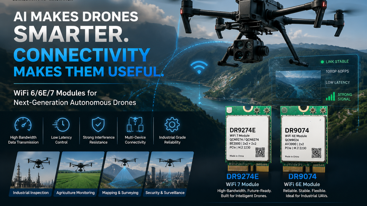
AI Makes Drones Smarter. Connectivity Makes Them Useful.

A drone performing industrial inspection, mapping, agriculture monitoring, or security missions needs to continuously exchange large amounts of data.

It needs to:

  • Stream high-resolution video in real time
  • Transfer sensor and vision data
  • Maintain low-latency control communication
  • Stay connected during high-speed movement

The wireless link is no longer just a communication channel.

It becomes the nervous system of an autonomous flying machine.


Why Drone Applications Need More Than Traditional Wireless Connectivity

Many UAV applications operate in challenging environments:

  • Long-range communication
  • High-speed mobility
  • Complex RF environments
  • Multiple drones working simultaneously
  • High-bandwidth AI data transmission

For these scenarios, peak speed alone is not enough.

A professional drone platform requires:

  • Stable connectivity
  • Low-latency response
  • Strong interference resistance
  • Reliable performance during long operation cycles

WiFi 6 and WiFi 7: Building the Wireless Foundation for Next-Generation UAVs

As drones become more intelligent, wireless technology must evolve to support higher demands.

Advanced WiFi platforms enable:

High-bandwidth AI applications

Real-time video streaming, multi-camera systems, and edge AI processing require fast and reliable data transmission.

Low-latency autonomous control

Faster response helps support autonomous navigation and mission-critical operations.

Multi-device communication

Future drone fleets and collaborative robotic systems will require efficient wireless networking.


524WiFi Industrial WiFi Modules for Intelligent Drone Platforms

For drone developers, selecting a wireless module is not only about maximum throughput.

Important considerations include:

  • Industrial-grade chipset platform
  • Driver and software support
  • Thermal stability
  • Flexible integration options
  • Long-term supply availability

Based on Qualcomm wireless platforms, Wallys provides WiFi solutions designed for industrial and AI-driven applications.


DR9274E WiFi 7 Module: Enabling Next-Generation Autonomous Drones

Powered by Qualcomm QCN9274 and QCN6274 platforms, the DR9274E WiFi 7 module is designed for applications requiring higher bandwidth, advanced connectivity, and future-ready wireless performance.

Potential applications include:

  • AI vision drones
  • Autonomous aerial robots
  • Industrial inspection UAVs
  • High-resolution video transmission systems

With WiFi 7 capabilities, it provides a powerful wireless foundation for intelligent devices requiring faster data exchange and more reliable connections.


DR9074 WiFi 6E Module: Reliable Connectivity for Industrial UAV Applications

Based on Qualcomm QCN9024, the DR9074 supports Tri-Band WiFi 6E operation across 2.4GHz, 5GHz, and 6GHz.

It is designed for applications requiring:

  • Stable wireless links
  • High-performance data transmission
  • Flexible frequency selection
  • Industrial deployment reliability

Suitable for:

  • Inspection drones
  • Mapping systems
  • Smart agriculture UAVs
  • Edge AI devices
Article content

Connecting the Future of Autonomous Flight

The future of drones will not only depend on better AI algorithms.

It will depend on the complete technology ecosystem:

AI provides intelligence. Sensors provide perception. Wireless connectivity enables action.

A smarter drone still needs a stronger wireless link.

At 524WiFi and Wallys, we are committed to providing Qualcomm-based WiFi 6 and WiFi 7 platforms for the next generation of drones, robotics, and edge AI applications.

The future of autonomous flight will not only be smarter.

It will be better connected.

Posted on

The Hidden Challenge in Robot Fleets: Roaming, Latency, and Wireless Stability

When people talk about autonomous robots, the conversation usually focuses on AI models, sensors, cameras, and navigation algorithms.

But there is another critical layer that often determines whether a robot system succeeds in real-world deployment:

Wireless connectivity.

A robot can have advanced AI capabilities, but without reliable communication, even the smartest robot may struggle in a dynamic industrial environment.

For large-scale robot fleets, connectivity is no longer just a networking feature. It becomes part of the robot’s operational reliability.

The Reality of Wireless Challenges in Robot Deployments

In warehouses, factories, farms, and outdoor industrial environments, robots are constantly moving.

An AMR (Autonomous Mobile Robot), for example, may need to:

  • Move across different areas with changing RF conditions
  • Maintain real-time communication with control systems
  • Upload high-resolution camera data
  • Receive navigation and task instructions
  • Coordinate with other robots in the same environment

During these operations, wireless networks face several challenges:

1. Roaming: Staying Connected While Moving

A robot moving through a large facility often needs to transition between multiple access points.

A poor roaming experience can cause:

  • Packet loss
  • Video interruption
  • Control delays
  • Temporary disconnection

For industrial robots, even a short communication interruption can affect efficiency and safety.

Advanced roaming mechanisms such as 802.11k/v/r help devices make faster and smarter roaming decisions by improving network awareness and reducing handover time.

However, successful roaming also depends on:

  • Proper RF planning
  • AP deployment strategy
  • Client behavior optimization
  • Network management

2. Latency: Every Millisecond Matters

Many industrial robot applications require real-time communication.

Examples include:

  • Remote monitoring
  • Vision-based inspection
  • Autonomous navigation
  • Robot fleet coordination

High latency can impact:

  • Motion control
  • Response time
  • Task execution efficiency

The challenge is not only achieving high throughput.

A network can provide high speed but still suffer from unstable latency due to:

  • Network congestion
  • Interference
  • Poor link quality
  • Inefficient routing

Reliable industrial wireless networks need predictable performance, not just peak speed.

3. Wireless Stability in Complex Environments

Industrial environments are very different from homes or offices.

Factories and outdoor deployments may include:

  • Metal structures causing reflections
  • Moving equipment blocking signals
  • Multiple wireless networks creating interference
  • Large numbers of connected devices

A robot fleet may experience changing wireless conditions every moment.

This requires networks that can adapt dynamically.

Important capabilities include:

  • Intelligent channel management
  • Interference detection
  • Dynamic path optimization
  • Mesh networking
  • Traffic prioritization

Why Traditional Wi-Fi Approaches Are Not Always Enough

A standard Wi-Fi deployment may work well for static users.

However, robot fleets introduce new requirements:

  • Mobility
  • High device density
  • Continuous connectivity
  • Low latency
  • Reliable uplink performance

The network needs to be designed around the robots’ movement and operational workflow.

Building the Wireless Foundation for Next-Generation Robots

The future of autonomous systems will depend on the combination of:

AI + Robotics + Reliable Connectivity

Advanced wireless technologies such as Wi-Fi 6 and Wi-Fi 7 bring important improvements:

  • Higher capacity
  • Better multi-device performance
  • Lower latency
  • Multi-band operation with MLO
  • Improved reliability in demanding environments

But technology alone is not enough.

Successful industrial deployments require:

  • The right wireless architecture
  • Proper RF optimization
  • Reliable hardware platforms
  • Long-term firmware support
  • Real-world validation

Final Thoughts

Autonomous robots are becoming smarter every day.

But intelligence alone does not guarantee successful deployment.

Behind every reliable robot fleet is a reliable communication infrastructure.

The next generation of industrial automation will not only depend on better AI algorithms — it will depend on wireless networks that can keep robots connected, responsive, and operational in the real world.

Reliable connectivity is the foundation that allows autonomous robots to truly become autonomous.