
 524WiFi™
524WiFi Pulse B7-02 Pro Plus – Wi-Fi 7 Tri-Band Router Board with 10GbE and SFP
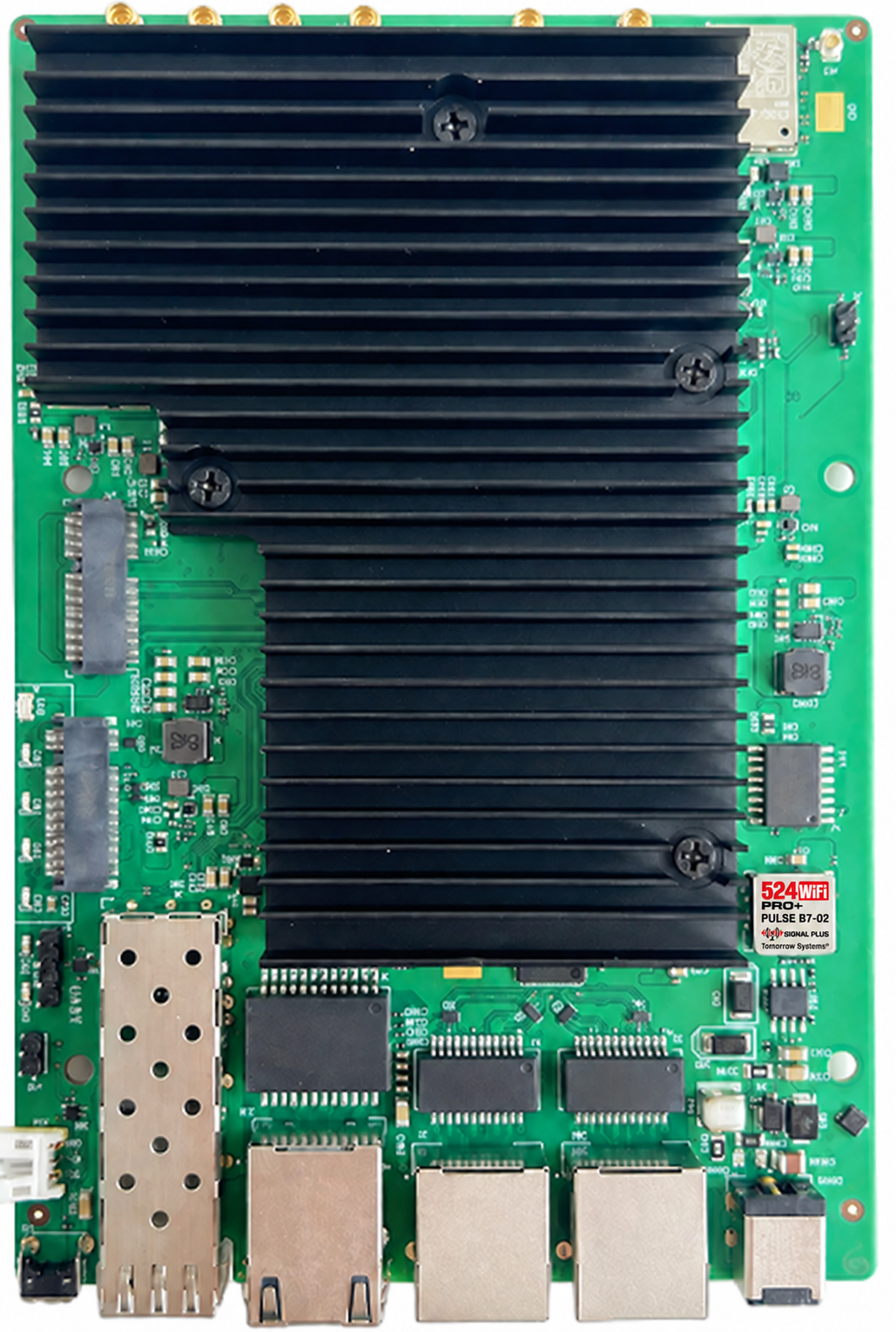
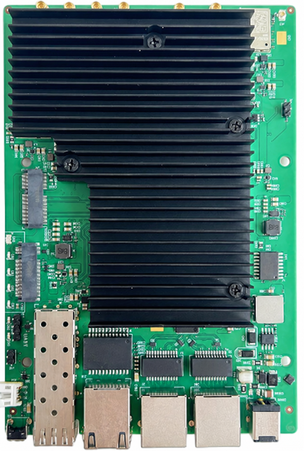
Wi-Fi 7 Tri-Band Router Board with 10GbE and SFP. Integrated multi-band access points with copper and optical uplink options. 2x2 radio configuration; 2 x 1GbE, 1 x 10GbE RJ45 and 1 x 10G SFP; 2 M.2 E-Key slots.
524WiFi™ Pro Plus — tuned for your wireless deployment

Our Pro Plus router boards are tuned for their intended wireless applications. Combine the radio architecture specified for this model with the right host, software configuration and antenna system to get the most from your installation. The technical sections below explain the settings, interfaces and configuration details relevant to this product.
524WiFi™ Signal Plus™ — make the most of your RF path

Signal Plus™ brings the antenna, operating band, polarization, connectors and installation together as one RF system. Match the antenna coverage to your application and keep the feed path short and low-loss to preserve useful signal in both directions. This model is part of our tuned product range; use its specified RF connector layout and supported bands when building your Signal Plus™ installation.
Choose matched antennas and cabling through 524WiFi™ and discuss your complete installation with our technical team. Explore our Pro Plus and Signal Plus™ approach.
Where this board fits
Integrated multi-band access points with copper and optical uplink options. The Qualcomm IPQ9574 platform and 2.4 + 5 + 6 GHz configuration define the role of this model in your network. Select the radio topology around the intended client population, channel plan and uplink design. A dedicated radio cell can be assigned its own SSID and security policy through the chosen software configuration.
Technical specification
| Model | Pulse B7-02 Pro Plus |
|---|---|
| Platform | Qualcomm IPQ9574 |
| Radio bands | 2.4 + 5 + 6 GHz |
| Configuration | 2x2 radio configuration; 2 x 1GbE, 1 x 10GbE RJ45 and 1 x 10G SFP; 2 M.2 E-Key slots |
| Software integration | Board-specific QSDK/Linux image and matching boot configuration |
| CPU architecture | Quad-core ARM Cortex-A73 |
|---|---|
| CPU clock | 2.2 GHz |
| Ethernet | 2 x 1GbE RJ45 + 1 x 10GbE RJ45 |
| Optical uplink | 1 x 10G SFP interface |
| Expansion | 2 x M.2 E-Key PCIe 3.0 slots |
| RF interface | 6 x MMCX |
| Theoretical PHY by band | 573.6 Mb/s at 2.4 GHz; 2882 Mb/s at 5 GHz; 5765 Mb/s at 6 GHz |
| Channel widths | Up to 40 / 160 / 320 MHz at 2.4 / 5 / 6 GHz respectively |
Detailed hardware and RF reference
Electrical, mechanical and interface detail
| Parameter | Pulse B7-02 |
|---|---|
| Processor | IPQ9574; four Cortex-A73 cores at 2.2 GHz |
| Memory interface | DDR4, 32-bit interface; delivered memory option as ordered |
| Copper and optical network | One 10GbE RJ45, one 10G SFP and two 1GbE ports |
| RF allocation | Three two-stream radio groups; six MMCX connectors |
| Engineering interfaces | UART and SGMII; two M.2 positions with purpose matched to the assembly |
| Power integration | Match DC/PoE input and M.2 slot wiring to the delivered board revision |
| Mechanical envelope | 161 x 110 x 16 mm |
| Environmental design | -40 to +70 C operating; -40 to +90 C storage |
RF engineering tables
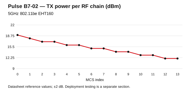
Model-specific datasheet reference points for RF design. TX is conducted power per RF chain; RX is input sensitivity. Configure channel, output power and antenna gain for the operating country.
5GHz 802.11be EHT160
| MCS | TX / chain (dBm) | RX sensitivity (dBm) |
|---|---|---|
| MCS0 | 19.0 | -88.0 |
| MCS1 | 18.0 | -86.0 |
| MCS2 | 17.0 | -83.0 |
| MCS3 | 17.0 | -80.0 |
| MCS4 | 16.0 | -78.0 |
| MCS5 | 16.0 | -76.0 |
| MCS6 | 15.0 | -74.0 |
| MCS7 | 15.0 | -71.0 |
| MCS8 | 14.0 | -68.0 |
| MCS9 | 14.0 | -66.0 |
| MCS10 | 13.0 | -63.0 |
| MCS11 | 13.0 | -60.0 |
| MCS12 | 12.0 | -56.0 |
| MCS13 | 12.0 | -53.0 |
Reference tolerance: ±2 dB.
6GHz 802.11be EHT320
| MCS | TX / chain (dBm) | RX sensitivity (dBm) |
|---|---|---|
| MCS0 | 19.0 | -82.0 |
| MCS1 | 18.0 | -79.0 |
| MCS2 | 17.0 | -76.0 |
| MCS3 | 17.0 | -73.0 |
| MCS4 | 16.0 | -70.0 |
| MCS5 | 16.0 | -67.0 |
| MCS6 | 15.0 | -63.0 |
| MCS7 | 15.0 | -61.0 |
| MCS8 | 14.0 | -58.0 |
| MCS9 | 14.0 | -56.0 |
| MCS10 | 13.0 | -53.0 |
| MCS11 | 13.0 | -51.0 |
| MCS12 | 12.0 | -49.0 |
| MCS13 | 12.0 | -47.0 |
Reference tolerance: ±2 dB.
Open full-size engineering chart
Pulse B7-02 engineering notes: radio, host and real deployment
Radio architecture and application
Integrated multi-band access points with copper and optical uplink options. The Qualcomm IPQ9574 platform and 2.4 + 5 + 6 GHz configuration define the role of this model in your network. Select the radio topology around the intended client population, channel plan and uplink design. A dedicated radio cell can be assigned its own SSID and security policy through the chosen software configuration.
Copper and optical network integration
Use the 10G SFP interface to integrate the board into an optical network and the 10GbE RJ45 connection for a high-speed copper path. Two 1GbE ports connect local Gigabit equipment. The six RF connectors serve the three two-stream radio cells. Plan separate 2.4, 5 and 6 GHz channel profiles in the firmware and match all antenna paths to the enclosure.
Theoretical PHY reference
Published maximum physical-layer rates by band, in Mb/s. Each bar represents its specified radio profile, channel width and spatial-stream configuration.
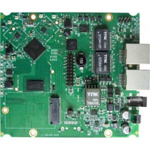
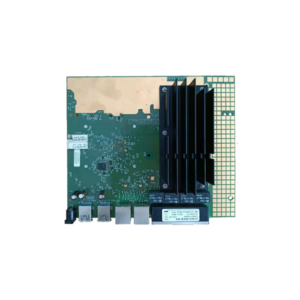
Hardware overview
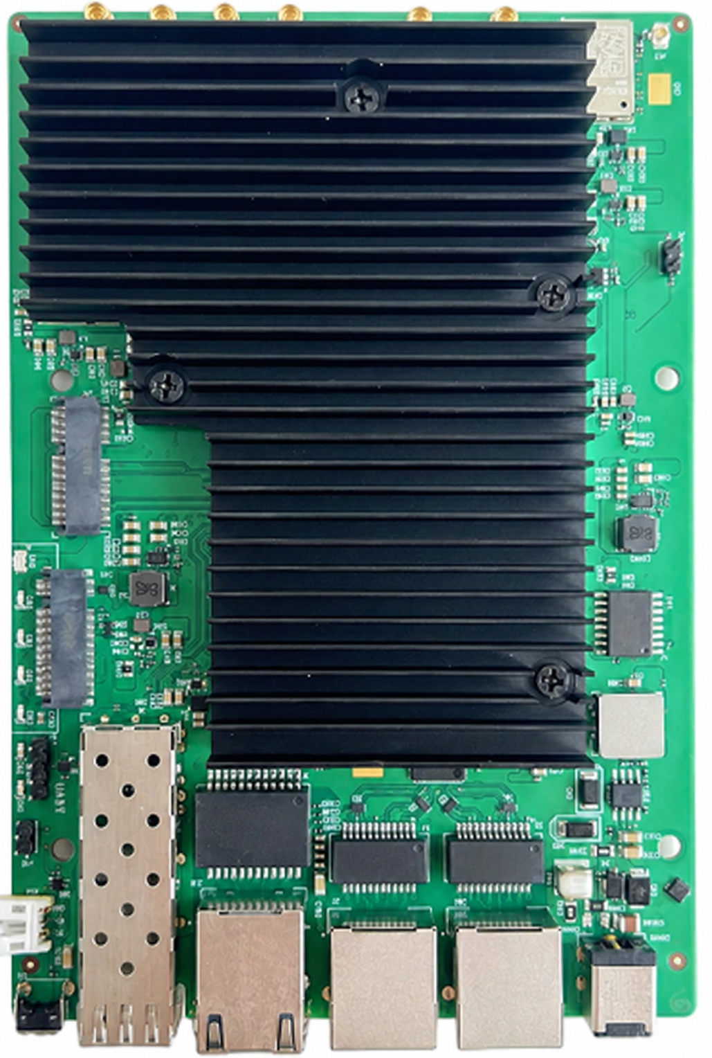
Linux, OpenWrt, firmware and board data
Use the complete board-specific system image for Pulse B7-02, including its bootloader, device tree, Ethernet switch/PHY configuration and radio calibration. Preserve the existing flash partition map and calibration partitions before an upgrade. Match the recovery procedure to the board revision and serial header.
| Integration item | Model-specific preparation |
|---|---|
| Platform | IPQ9574; quad-core Cortex-A73 at 2.2 GHz |
| Network verification | 10GbE RJ45 + 10G SFP + 2 x 1GbE |
| Image identity | Record release/build, board revision, image checksum and the partition layout. |
| OpenWrt / QSDK workflow | Select a board-targeted build approved for the delivered assembly; radio-driver support is only one part of the complete image. |
| First boot | Capture the UART boot log; verify memory, flash, Ethernet link negotiation and each installed radio. |
Model documentation and data
Pulse B7-02 technical reference and integration guide · Download RF reference data (CSV)
Installation checklist
- Prepare the host or enclosure, mounting points and management access for the model specified above.
- Match the power supply and cooling to the complete assembly and the technical configuration.
- Secure the hardware and connect the appropriate RF paths, Ethernet interfaces and peripherals.
- Start with the revision-matched software image, then configure the operating country, radio channels and network role.
- Verify client association and traffic in both directions; retain the working image and deployment record.
Start with the network role: access-point coverage, an embedded gateway or an engineering platform. Plan the Ethernet uplink, client density and management access together. For multiple radio cells, assign channels and antenna positions as part of one installation plan. Keep management access available while bringing up each interface and retain a known working configuration for recovery.
For the hardware installation, use the correct mounting points and provide clearance around the heatsink, connectors and adjacent components. Size the power supply for the complete assembly, including optional radio modules and peripherals. Provide airflow over the active components and route RF cables so their connectors remain free of mechanical strain.
Signal Plus™: antenna and RF-path integration
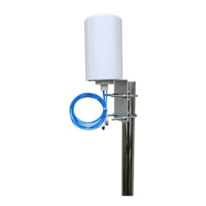
Signal Plus™ brings the antenna, operating band, polarization, connectors and installation together as one RF system. For Pulse B7-02, start with the 2.4 + 5 + 6 GHz configuration and the RF interfaces in the technical table. Match the coverage pattern to your site and preserve useful signal with short, low-loss cable runs.
Ask our technical team to match antennas and RF accessories to your installation.
Troubleshooting quick path
| Hardware recognition | Review the boot log and detected interfaces against the hardware configuration above. |
|---|---|
| Firmware and radio initialization | Match the driver, firmware and calibrated board data to the physical revision and host image. |
| Wireless association | Review the country profile, band, channel, security settings and antenna connections. |
| Sustained traffic | Check power stability, component temperature, negotiated link rates and RF path quality under the intended load. |
| Engineering review | Share the Pulse model, hardware revision, software version and initialization logs with our support team. |
Deployment testing and acceptance
Use the following commissioning procedure for Pulse B7-02. This is a test method, separate from the theoretical PHY specifications and datasheet RF references above.
| Step | Record and verify |
|---|---|
| Baseline | Model/revision, firmware build, host CPU, uplink speed, channel width, country profile, antennas and client spatial streams. |
| Link verification | Capture negotiated PHY, RSSI per chain and noise/retry statistics before sustained traffic. |
| Wired reference | Measure the wired path first; select a server link appropriate to 573.6 / 2882 / 5765 Mb/s by band. |
| Traffic test | Run TCP in each direction, then concurrent clients; record duration, CPU load, temperatures and retransmissions. |
| Site acceptance | Repeat at the intended mounting positions; save results with the exact configuration for comparison. |
FAQ
Where does this model fit in a network?
Use this embedded board as the hardware foundation for an access point or gateway. Select the enclosure, power supply and antennas around the port layout and radio configuration in the technical tables.
How do I choose the software package?
Use the package matched to this model and hardware revision. Share your host and kernel version with technical support so the driver, firmware, board data and installation procedure can be reviewed together.
How should I select antennas?
Match antenna bands and RF connectors to the stated configuration. Select directional or omnidirectional coverage for the installation, preserve the intended MIMO paths and use short, suitably rated pigtails. Include enclosure mounting and cable routing in the RF plan.
What does the PHY figure describe?
It describes the theoretical physical-layer link rate for the specified radio profile. Select the corresponding channel width, spatial streams and compatible client configuration when planning around that figure. Document practical application tests separately with their complete setup.
How do I prepare a repeatable deployment?
Keep a record of the working image, configuration, hardware revision, power supply, antenna configuration and deployment country. Validate radio initialization, client association and sustained traffic in the intended enclosure before rolling the configuration out to additional units.
What should I send for engineering support?
Send the Pulse model code, intended application, host or board revision, software version, antenna arrangement and relevant diagnostic logs. Our technical team can then review the complete installation.
Final model identification and code table
| 524WiFi | Product brand |
|---|---|
| Pulse | Wireless integration product family |
| B | Embedded router board |
| 7 | Wi-Fi generation family; exact radio capabilities are specified above |
| 02 | Configuration identifier within this family |
| Pro Plus | Tuned professional series |
| Ordering SKU | 524WIFI-PULSE-B7-02-PP |
Send us Pulse B7-02 together with your intended country, host or enclosure, antenna plan and required software environment. We can review the configuration and recommend appropriate RF accessories for your project. Contact 524WiFi™ technical support.



Reviews
There are no reviews yet.