

Posted on — Leave a comment

How to Design a Reliable Long-Range Wireless Link for Agricultural Drones (WiFi 6/7 Selection Guide)

If you’ve deployed drones for crop spraying, field mapping, or orchard inspection over any real distance, you’ve probably run into this: the link holds fine at 200 meters, then starts dropping commands or breaking up video well before you hit the range the datasheet promised. It’s rarely a bad chip. It’s almost always an architecture problem.

This guide walks through why long-range agricultural links behave differently from indoor or short-range WiFi deployments, what actually determines reliability at range, and how to select hardware — control-side and video-side — that holds up in the field.

Why Agricultural Drone Links Are a Different Problem

Most WiFi hardware is designed and benchmarked for indoor, short-range, high-density environments — offices, warehouses, retail. Agricultural drone deployments invert almost every one of those assumptions:

  • Distance is the default, not the exception. A single control link routinely needs to cover several hundred meters to a few kilometers across open farmland or orchards.
  • There’s no multipath to lean on. Indoor WiFi benefits from reflections off walls and ceilings. Open fields don’t offer that — and offer very little shielding from other interference either.
  • Control and video have opposite requirements. Control commands are small, frequent packets that need low, consistent latency and near-zero loss. Video (especially 4K, multispectral, or thermal payloads) needs sustained bandwidth and can tolerate some jitter. Serving both well on one link is hard.
  • One-to-many is common. A single ground station frequently needs to manage multiple aircraft flying formation or covering different zones of the same field, which means the AP side has to handle concurrent, fast-moving clients — not a single static link.
  • Power is capped by regulation, not by ambition. ISM-band transmit power and antenna gain both have legal ceilings. You can’t out-power your way to more range.

The Five Things That Actually Determine Reliability at Range

1. Band Strategy: Split the Link, Don’t Pick One Band

2.4GHz diffracts better around terrain, crops, and structures, which is why it’s traditionally the default choice for long-range control links. 5GHz and 6GHz offer far more spectrum and fewer competing signals, which is exactly what high-resolution video needs.

The reliable pattern in the field isn’t choosing one band for everything — it’s running a split architecture: control on 2.4GHz, video on 5GHz or 6GHz. That’s a strong argument for radio hardware where the band configuration is flexible (single-band, dual-band, or switchable tri-band) rather than fixed to one band at the factory.

2. Modulation and Spatial Streams: Know What They Actually Control

Specs like 4096-QAM and multi-stream MU-MIMO are real and useful — but they define your near-field ceiling, not your far-field floor. As distance increases and signal-to-noise ratio drops, the link automatically falls back to lower-order modulation regardless of the chip’s peak capability.

When evaluating hardware for a long-range deployment, the number that matters isn’t the “Gbps peak” on the datasheet. It’s the rate-adaptation curve under low SNR, and specifically the minimum usable data rate at the outer edge of your intended range. That’s the number that tells you whether video will break up or commands will get dropped when the aircraft is farthest from the ground station — which is exactly when you need the link most.

3. MLO (Multi-Link Operation): Redundancy, Not Traffic Splitting

WiFi 7 introduced Multi-Link Operation, which lets a device establish links across multiple bands or channels at once. There’s a common misconception worth clearing up here: MLO isn’t a way to route control traffic on one band, video on another, and backhaul on a third, each running independently.

What MLO actually does is transmit the same data redundantly across multiple links simultaneously, so that if one link momentarily fades or gets interfered with, the other link covers for it — improving reliability and reducing effective latency. For agricultural drones, where a lost link is often the trigger for a return-to-home failsafe, that kind of redundancy has real operational value, not just a spec-sheet checkbox.

4. Topology: Point-to-Point vs. One-to-Many

A single aircraft doing long-range mapping or inspection is often best served by a point-to-point link — a directional antenna setup trading beamwidth for range and stability. But if a ground station needs to manage multiple aircraft or ground terminals simultaneously, the AP side needs OFDMA multi-user scheduling and fast roaming/handoff behavior, or you’ll see queuing delay whenever multiple aircraft check in around the same time.

Know which problem you’re actually solving before you pick hardware — they call for different radio capabilities.

5. Form Factor: Airborne and Ground-Side Needs Diverge

The airborne side is constrained by payload weight and available power, so it needs a small, low-power radio module that can be integrated directly into a flight controller or gimbal payload — with just enough band flexibility to serve the control link without unnecessary weight or draw.

The ground station side is a different design problem entirely: it needs to aggregate multiple client connections, handle higher sustained throughput, and typically needs wired backhaul (Ethernet, sometimes 10GbE) to move the collected video and telemetry off to a local server or the cloud. That usually points toward a board-level platform rather than a compact module.

Mapping Hardware to the Problem

Once you’ve worked through the five factors above, hardware selection becomes a matter of matching platform to role rather than chasing a single “best” spec sheet.

Airborne / terminal-side radio module. You want something small, power-efficient, and configurable — ideally a module where you can select or trim the band configuration (single-band 2.4GHz for a dedicated control radio, or dual-band where the payload allows) without carrying unused radio hardware and power draw. This is the role a WiFi 7 M.2 module built on a chipset like Qualcomm’s QCN9274/QCN6274 platform is designed for, with configurations spanning single-band, dual-band, and 4×4 single-band variants depending on what the airframe needs.

Ground-station aggregation board. This is where you want a flagship-class multi-band platform — four simultaneous bands, wide channels (up to 320MHz), high-order modulation (4096-QAM), multiple M.2 slots for additional radio cards, and dual 10GbE-class wired uplinks. This tier handles concurrent multi-aircraft connections, dynamic channel selection (AFC) to work around interference, and reliably backhauling the aggregated video streams to wherever they’re processed.

Edge gateway with onboard compute. For deployments where you want to do video processing or stream aggregation closer to the field — rather than pushing everything raw to the cloud — a tri-band gateway platform with high-speed wired I/O (dual 10GbE + multiple 2.5GbE) and an onboard AI accelerator tuned for networking workloads is the better fit. It handles wireless backhaul while also doing local compute, cutting the bandwidth pressure on the uplink.

A Practical Decision Order

When you’re actually speccing a system, work through it in this order:

  1. Point-to-point or one-to-many? This determines whether OFDMA and fast roaming on the ground-station side are must-haves or nice-to-haves.
  2. Does the control link need to be physically separated from the video link? This determines whether a single-band module or a multi-band board is the right call for each end of the system.
  3. What are the payload’s power and space constraints? This determines module-level vs. board-level hardware on the airborne side.
  4. Does the back end need edge compute or multi-stream video aggregation? If yes, prioritize a gateway platform with onboard AI acceleration and high-speed wired I/O.

FAQ

Is 2.4GHz or 5GHz better for a long-range drone control link? 2.4GHz generally holds up better over distance and around obstructions like terrain or crop canopy, which is why it’s the more common choice for the control link specifically. 5GHz and 6GHz are typically reserved for the video link, where the extra bandwidth matters more than raw range.

Do I need WiFi 7, or is WiFi 6 enough? It depends on whether you need MLO’s link redundancy and whether your video payload actually needs the extra bandwidth WiFi 7’s wider channels provide. Many long-range control links work fine on WiFi 6; WiFi 7 becomes more valuable as video resolution, aircraft count, or reliability requirements increase.

What’s the actual benefit of MLO for a drone link? Redundancy. The same data is sent across multiple links at once, so a momentary fade on one link doesn’t cost you the connection — it isn’t a way to assign different traffic types to different bands independently.

Should the airborne radio and the ground-station radio be the same hardware? No — they’re solving different problems. The airborne side prioritizes size, weight, and power; the ground station prioritizes aggregate throughput, multi-client handling, and wired backhaul capacity.


If you’re evaluating or redesigning the wireless subsystem in a drone flight-control or video-transmission stack — or migrating an existing deployment from WiFi 5/6 to WiFi 7 — reach out to info at 524wifi.com or .net. We build radio hardware across all three tiers described above and can walk through the specifics of your deployment.

Posted on

How to set the APN in a cellular module?

What is an APN, why does it matter? 

An APN (Access Point Name) is the gateway configuration that tells your cellular module which network path to use when connecting to the internet or a private data network. Think of it as the “address” your device hands to the carrier to establish a data session. It determines routing, IP assignment, and in many cases, what security policies apply to your traffic.

APNs exist because carriers need to route data traffic to different destinations: a consumer browsing social media, a fleet vehicle reporting GPS, and a medical device uploading readings all have very different requirements – and the APN is how the network tells them apart.

In IoT deployments, leaving the APN on auto-detect is a common mistake. Manually setting it ensures your device consistently connects to the right context, especially critical when using IoT SIMs, private APNs with fixed IPs, or roaming SIMs where auto-selection can land you on a suboptimal or even incorrect bearer. A wrong or missing APN means no data, silent failures, and hours of debugging that could have been avoided with a single AT command. 

How to set “my APN” in a cellular module?

By default, cellular modules come without a pre-defined APN (Access Point Name). It is however best practice to set this to the correct value to tell the module how to get online

Via AT commands:

Check if any APN is set:

AT+CGDCONT? // Query APN
+CGDCONT: 1,"IPV4V6","","0.0.0.0.0.0.0.0.0.0.0.0.0.0.0.0",0,0,0,0,,,,,,,,,,"",,,,0

To set an APN:

AT+CGDCONT=1,"IP-VERSION","YOURAPN"

Example:

AT+CGDCONT=1,"IPV4V6","techship.com" // Set APN
OK
AT+CGDCONT? // Query APN
+CGDCONT: 1,"IPV4V6","techship.com","0.0.0.0.0.0.0.0.0.0.0.0.0.0.0.0",0,0,0,0,,,,,,,,,,"",,,,0 
AT+CFUN=1,1 // Restart the module for settings to take effect

Via Windows GUI:

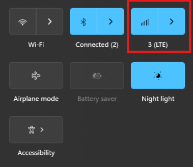
The connection manager settings and controls can be found and accessed on Windows desktop start menu through the network icon (see picture)

The Cellular tab can be found in Windows system settings and the connection APN details can be manually entered through “Advanced options”

Via Linux ModemManager/NetworkManager:

Using NetworkManager and ModemManager in Linux to automatically establish a connection and configure IP details

In this article we will show how to set up NetworkManager to automatically configure, establish the cellular data connection in your system.

NetworkManager and ModemManager are open source tool for Linux to manage several types of networks and interfaces such as ethernet, wifi, etc. It can also manage cellular WWAN interfaces through the ModemManager tool.
It is hosted by the Freedesktop.org community and driven by Aleksander Morgado and other contributors. please visit https://wiki.gnome.org/Projects/NetworkManager and https://www.freedesktop.org/wiki/Software/ModemManager/ for latest information, source code, API reference manuals, debugging tips, contribution, mailing list etc.

ModemManager is capable of communicating over several types of device control channels such as QMI/RMNET, MBIM, MODEM / AT command etc. But support for vendor proprietary or out-of-kernel drivers are none or very limited. Such drivers are gobinet, simcom_wwan and other drivers provided by the vendors directly.

Many Linux distributions have NetworkManager and ModemManager pre-installed or they can typically easily be installed through the systems package manager.
In Ubuntu for example apt can install it for you by command if not already installed:
apt install network-manager

Check with commands below that you have both tools installed in system and their versions.
NetworkManager -V
ModemManager -V

ModemManager (and NetworkManager) are continuously developed for better compatibility with the cellular devices, therefore it is recommend to use a recent version of the tools and in case of problem situations, evaluate the latest versions from source and check the mailing list archives for possible discussions on the problem experienced.

Keep in mind that NetworkManager and ModemManager projects are not directly developed or driven by the cellular device vendors and the compatibility with the device you aim to use can be limited. Some vendors contribute with code to make their devices fully compatible, while others don’t. Many cellular devices can be set to expose standardized types of USB network interface and control channel such as MBIM interface by USB-IF or the Qualcomm proprietary interface QMI that ModemManager will try to identify, and often manage to work successfully with but there are exceptions also.

Both NetworkManager and ModemManager have command line interfaces (nmcli and mmcli respectively) where you can interact with the management tools.

Have ModemManager list all the cellular device it has detected. Here we use the Alcatel IK41 series with MBIM interface in this example:
mmcli –list-modems
/org/freedesktop/ModemManager1/Modem/0 [Alcatel] Mobilebroadband

General details and status of them modem can be listed with “–modem” option.
mmcli –modem=0
—————————–
General | dbus path: /org/freedesktop/ModemManager1/Modem/0
| device id: 998e478c5b14c75e16bffe6abaacabef22fb2f5b
—————————–
Hardware | manufacturer: Alcatel
| model: Mobilebroadband
| firmware revision: MPSS.JO.2.0.2.c1.7-00004-9607_
| carrier config: default
| h/w revision: 0
| supported: gsm-umts, lte
| current: gsm-umts, lte
| equipment id:
—————————–
System | device: /sys/devices/pci0000:00/0000:00:14.0/usb3/3-1
| drivers: option1, cdc_mbim
| plugin: Generic
| primary port: cdc-wdm0
| ports: cdc-wdm0 (mbim), ttyUSB0 (at), ttyUSB2 (at), wwan0 (net),
| ttyUSB1 (qcdm)
—————————–
Status | lock: sim-pin
| unlock retries: sim-pin (3)
| state: locked
| power state: on
| signal quality: 0% (cached)
—————————–
Modes | supported: allowed: 2g; preferred: none
| allowed: 3g; preferred: none
| allowed: 4g; preferred: none
| allowed: 2g, 3g; preferred: 3g
| allowed: 2g, 3g; preferred: 2g
| allowed: 2g, 4g; preferred: 4g
| allowed: 2g, 4g; preferred: 2g
| allowed: 3g, 4g; preferred: 3g
| allowed: 3g, 4g; preferred: 4g
| allowed: 2g, 3g, 4g; preferred: 4g
| allowed: 2g, 3g, 4g; preferred: 3g
| allowed: 2g, 3g, 4g; preferred: 2g
| current: allowed: 2g, 3g, 4g; preferred: 2g
—————————–
Bands | supported: egsm, dcs, pcs, g850, utran-1, utran-8, eutran-1, eutran-3,
| eutran-7, eutran-8, eutran-20, eutran-28
| current: egsm, dcs, pcs, g850, utran-1, utran-8, eutran-1, eutran-3,
| eutran-7, eutran-8, eutran-20, eutran-28
—————————–
IP | supported: ipv4, ipv6, ipv4v6
—————————–
SIM | dbus path: /org/freedesktop/ModemManager1/SIM/0

Check that the cellular device is managed by NetworkManager by not having state “unmanaged” listed for it.
nmcli device status
DEVICE TYPE STATE CONNECTION
cdc-wdm0 gsm disconnected —
enp3s0 ethernet unmanaged —
lo loopback unmanaged —

Now you should create a connection profile in NetworkManager for your specific network carrier and SIM card with the “nmcli connection add” command:
For example:
nmcli connection add type gsm ifname ‘*’ con-name ‘3-sweden’ apn ‘data.tre.se’ connection.autoconnect yes gsm.pin 0000

– type is gsm for all typical cellular connections unless it is of cdma type.
– ifname is the control interface name, in this case cdc-wdm0, wildcard can be used also to have it autoselect.
– con-name is the profile name you want to give it.
– apn is provided by your network carrier and tells the modem what attach point it should use for the data connection.
– connection.autoconnect set to yes will make NetworkManager always try to auto connect and maintain this profile connection.
– gsm.pin lets you provide a pin code for the SIM card, that NetworkManager will try to use if PIN check is enabled for SIM card.

There are several additional commands and attributes available such as username and password settings for the APNs etc. Refer to the NetworkManager help and manual pages for full details on the commands.

If successful you should receive a reply similar to this one:
Connection ‘3-sweden’ (cad6fcbf-2cb1-4796-b7e6-67b9f9635aef) successfully added.

You can check the status now by command:
nmcli device status
DEVICE TYPE STATE CONNECTION
cdc-wdm0 gsm connected 3-sweden
enp3s0 ethernet unmanaged —
lo loopback unmanaged —

Where connected should be listed as state if the connection establishment was successful.

If the connection is not successful or you want more details about the device and connection you can check commands:

You can list the current status with command:
nmcli radio
WIFI-HW WIFI WWAN-HW WWAN
enabled enabled enabled enabled

nmcli device show cdc-wdm
GENERAL.DEVICE: cdc-wdm0
GENERAL.TYPE: gsm
GENERAL.HWADDR: (unknown)
GENERAL.MTU: 1500
GENERAL.STATE: 100 (connected)
GENERAL.CONNECTION: 3-sweden
GENERAL.CON-PATH: /org/freedesktop/NetworkManager/ActiveConnection/18
IP4.ADDRESS[1]: 2.68.73.130/30
IP4.GATEWAY: 2.68.73.129
IP4.ROUTE[1]: dst = 2.68.73.128/30, nh = 0.0.0.0, mt = 700
IP4.ROUTE[2]: dst = 0.0.0.0/0, nh = 2.68.73.129, mt = 700
IP4.DNS[1]: 80.251.201.177
IP4.DNS[2]: 80.251.201.178
IP6.ADDRESS[1]: 2a02:aa1:1017:6d11:1060:3dff:feac:e92f/64
IP6.ADDRESS[2]: 2a02:aa1:1017:6d11:6474:7254:7b72:eb09/64
IP6.GATEWAY: 2a02:aa1:1017:6d11:21e6:9049:6cfb:8ac3
IP6.ROUTE[1]: dst = ff00::/8, nh = ::, mt = 256, table=255
IP6.ROUTE[2]: dst = 2a02:aa1:1017:6d11::/64, nh = ::, mt = 700
IP6.ROUTE[3]: dst = ::/0, nh = fe80::21e6:9049:6cfb:8ac3, mt = 1024
IP6.ROUTE[4]: dst = 2a02:aa1:1017:6d11::/64, nh = ::, mt = 256
IP6.ROUTE[5]: dst = ::/0, nh = 2a02:aa1:1017:6d11:21e6:9049:6cfb:8ac3, mt = 700
IP6.DNS[1]: 2a02:aa0::55
IP6.DNS[2]: 2a02:aa0::56

nmcli connection show
NAME UUID TYPE DEVICE
3-sweden e946017f-2e9c-477b-89ad-4c31e7331d65 gsm cdc-wdm0

Ifconfig should now show the related IP address details already set to the network interface by NetworkManager:
ifconfig
wwan0: flags=4291 mtu 1500
inet 2.68.73.130 netmask 255.255.255.252 broadcast 2.68.73.131
inet6 2a02:aa1:1017:6d11:6474:7254:7b72:eb09 prefixlen 64 scopeid 0x0
inet6 2a02:aa1:1017:6d11:1060:3dff:feac:e92f prefixlen 64 scopeid 0x0
ether 12:60:3d:ac:e9:2f txqueuelen 1000 (Ethernet)
RX packets 186 bytes 10886 (10.8 KB)
RX errors 0 dropped 0 overruns 0 frame 0
TX packets 5 bytes 480 (480.0 B)
TX errors 0 dropped 0 overruns 0 carrier 0 collisions 0

You can now for example test the connection over the network interface by sending ping requests.
Testing IPV4 connection:
ping -4 -I wwan0 8.8.8.8
PING 8.8.8.8 (8.8.8.8) from 2.68.73.130 wwan0: 56(84) bytes of data.
64 bytes from 8.8.8.8: icmp_seq=1 ttl=118 time=55.8 ms
64 bytes from 8.8.8.8: icmp_seq=2 ttl=118 time=45.4 ms
64 bytes from 8.8.8.8: icmp_seq=3 ttl=118 time=42.9 ms
— 8.8.8.8 ping statistics —
3 packets transmitted, 3 received, 0% packet loss, time 2003ms
rtt min/avg/max/mdev = 42.918/48.053/55.845/5.601 ms

Testing IPV6 connection: (if your cellular device, network subscription and APN supports it)
ping -6 -I wwan0 2600::
PING 2600::(2600::) from 2a02:aa1:1017:6d11:1060:3dff:feac:e92f wwan0: 56 data bytes
64 bytes from 2600::: icmp_seq=1 ttl=46 time=172 ms
64 bytes from 2600::: icmp_seq=2 ttl=46 time=171 ms
64 bytes from 2600::: icmp_seq=3 ttl=46 time=169 ms
64 bytes from 2600::: icmp_seq=4 ttl=46 time=168 ms
— 2600:: ping statistics —
4 packets transmitted, 4 received, 0% packet loss, time 3004ms
rtt min/avg/max/mdev = 167.921/170.037/172.272/1.651 ms

The connection is successful and automatic reconnect is working when testing to unplug and plug in the device again.
For additional configurations, commands and available attributes, please relate to the manual pages for NetworkManager and ModemManager.

Troubleshooting logs:
NetworkManager and ModemManager write log messages to the Linux syslog file /var/log/syslog.
In case of problems with establishing a cellular data connection, please copy the logfile after the problem have appeared and include it in a Techship technical support ticket.

In some situations more detailed debug logs are needed, these can be acquired by changing the log levels for NetworkManager and ModemManager and run them manually.

To capture debug logs, please first disable and stop the normal services:
systemctl stop NetworkManager ModemManager
systemctl disable NetworkManager ModemManager

Run them manually in background with debug level set:
/usr/sbin/ModemManager –log-level=DEBUG &> /dev/null &
/usr/sbin/NetworkManager –log-level=DEBUG &

Reproduce the cellular data connection problem.
Once completed, kill the processes:
killall -TERM NetworkManager ModemManager

Copy the relate messages in syslog to a mm-nm-sys-debug.log logfile:
grep -E ‘ModemManager|NetworkManager|systemd|dbus-daemon|dhclient’ /var/log/syslog > mm-nm-sys-debug.log

Activate and start the services again:
systemctl enable NetworkManager ModemManager
systemctl start NetworkManager ModemManager

Include the mm-nm-sys-debug.log in a technical support ticket at Techship.com where you describe the issue in details and include other relevant information also such as kernel version, ModemManager and NetworkManager versions, dmesg log etc.

Posted on

How to configure a Wi-Fi network using IW and IP utilities with wpa_supplicant


IW is a configuration utility for wireless devices and supports most if not all drivers implemented officially in the Linux kernel. It can be used to setup and connect to wifi networks as well as configure access points/hotspots on supported modems. It replaces the older iwconfig utility which is not recommended for use.
The IP utility is a routing tool that is used to configure network interfaces on your linux host and to configure bridges between devices.  

To list all wireless devices the command iw dev or /sbin/iw dev can be used and the response could look something like this:

phy#0

        Interface wlp1s0

                ifindex 4

                wdev 0x1

                addr 04:f0:21:3f:0a:a3

                type managed

                txpower 23.00 dBm

                multicast TXQ:

                        qsz-byt qsz-pkt flows   drops   marks   overlmt hashcol tx-bytes        tx-packets

                        0       0       0       0       0       0       0       0               0

To make sure that the device is up and running issue:
ip link show wlp1s0

In this case, the wireless device is wlp1s0 and for which command return the following:

4: wlp1s0: UP> mtu 1500 qdisc noqueue state DOWN mode DORMANT group default qlen 1000

    link/ether 04:f2:24:3d:2b:d9 brd ff:ff:ff:ff:ff:ff

If the device is not active and ‘UP’ it can be set active using:

sudo ip link set wlp1s0 up

To see if the device  is connected to a network or not, issue:

iw wlp1s0 link

Connected to b3:fa:d4:32:64:12 (on wlp1s0)

        SSID: 524wifi-5G

        freq: 5200

        RX: 4602636 bytes (28600 packets)

        TX: 17664 bytes (150 packets)

        signal: -53 dBm

        rx bitrate: 360.0 MBit/s VHT-MCS 8 40MHz short GI VHT-NSS 2

        tx bitrate: 6.0 MBit/s

        bss flags:      short-slot-time

        dtim period:    3

        beacon int:     100

If not, it simply returns ‘Not connected’

To see available wifi networks in range use the scan function of the modem:

iw wlp1s0 scan

********************SNIPPET*******************

BSS d0:21:f9:32:64:bb(on wlp1s0)

        last seen: 7092.798s [boottime]

        TSF: 1755910453320 usec (20d, 07:45:10)

        freq: 5220

        beacon interval: 100 TUs

        capability: ESS Privacy SpectrumMgmt ShortSlotTime RadioMeasure (0x1511)

        signal: -71.00 dBm

        last seen: 1704 ms ago

        Information elements from Probe Response frame:

  SSID: Techship

        Supported rates: 6.0* 9.0 12.0* 18.0 24.0* 36.0 48.0 54.0

        DS Parameter set: channel 44

 Country: SE     Environment: Indoor/Outdoor

                Channels [36 – 36] @ 23 dBm

                Channels [40 – 40] @ 23 dBm

                Channels [44 – 44] @ 23 dBm

                Channels [48 – 48] @ 23 dBm

                Channels [52 – 52] @ 23 dBm

                Channels [56 – 56] @ 23 dBm

                Channels [60 – 60] @ 23 dBm

                Channels [64 – 64] @ 23 dBm

                Channels [100 – 100] @ 30 dBm

                Channels [104 – 104] @ 30 dBm

                Channels [108 – 108] @ 30 dBm

                Channels [112 – 112] @ 30 dBm

                Channels [116 – 116] @ 30 dBm

                Channels [120 – 120] @ 30 dBm

                Channels [124 – 124] @ 30 dBm

                Channels [128 – 128] @ 30 dBm

                Channels [132 – 132] @ 30 dBm

                Channels [136 – 136] @ 30 dBm

                Channels [140 – 140] @ 30 dBm

        RSN:     * Version: 1

                 * Group cipher: CCMP

                 * Pairwise ciphers: CCMP

                 * Authentication suites: PSK

                 * Capabilities: 1-PTKSA-RC 1-GTKSA-RC (0x0000)

        BSS Load:

                 * station count: 4

                 * channel utilisation: 19/255

                 available admission capacity: 31250 [32us]

********************SNIPPET*******************

Make sure that the country parameter is correct, if not you can set the country code with the following:
sudo iw reg set SE

This ensures that the modem follows country-specific frequency regulations!

To connect to a password protected network (e.g. WPA version 1,2 or 3) a configuration file called wpa_supplicant.conf that handles the security protocol is needed:
 

wpa_passphrase SSID >> /etc/wpa_supplicant.conf

enter wifi password and hit enter

The generated output would look something like this:

network={

        ssid=”524wifi-5G”

        #psk=”password”

        psk=5abc7d89f8e9d8c7aa6b8c7d223e520d26a13e932bf0acb1d4580461d6d2ba8d

}

 If sudo privileges aren’t enough; login as root with: sudo -s and issue the above again.

When the file has been created it can be run in the background using:

sudo wpa_supplicant -B -D wext -i wlan0 -c /etc/wpa_supplicant.conf

Then check once more if the connection was successful with:
 iw wlp1s0 link

The last step is to request an IP adress from the host server via DHCP client:

dhclient wlp1s0

Issue ip addr show wlp1s0 to check assigned ip address and

if you have recieved one you are ready to surf!

For further information and features see:

en:users:documentation:iw [Linux Wireless] (kernel.org)
wpa_supplicant – ArchWiki (archlinux.org)
networking:iproute2 [Wiki] (linuxfoundation.org)

Note: Tested on Ubuntu 22.04 kernel 5.19