Exciting News: 524 WiFi Driver DR5018 Series Now Supports OpenWRT
524WiFi and WallysTech are proud to announce that our DR5018 series, including models DR5018, DR5018M, DR5018M-5G, and DR5018M-6G, now supports OpenWRT and Linux version 6.6.35. This update brings a new level of flexibility and control to your networking infrastructure, allowing you to leverage the robust features and active community support of OpenWRT. Whether you’re operating in the 5G or 6G spectrum, the DR5018 series is designed to meet the demands of modern networking environments.
Outstanding Hardware Performance of DR5018M
Under WallysTech’s own firmware, the DR5018M model stands out with its impressive hardware performance. It excels in Point-to-Point (PtP) applications, delivering remarkable connectivity over distances of 1.5km and 3.3km. This makes it an ideal choice for businesses requiring robust and reliable long-distance networking solutions.
DR5018M (Original Version)
1.Compact size
2.Customizable bottom board for enhanced flexibility
Dual-core ARM 64-bit A53 processor clocked at 1.0GHz
1GB DDR L3L system memory
8MB NOR Flash, 256MB NAND Flash
Dual onboard 2.4GHz radios with up to 573Mbps physical data rate
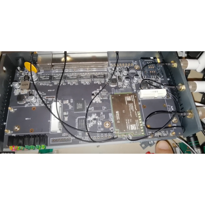
M.2 card slot for QUECTEL RM 500Q-GL 5G module
M.2 card slot for QCN9074 WIFI 6E Card
M.2 card slot for QCN6122-6E Card
M.2 card slot for QCN6102-5GCard
Supports Openwifi
New DR5018M (Updated Version)
1.New base board with onboard 5G/6G selectable capability
2.Added 2.5G Ethernet port
Dual-core ARM 64-bit A53 processor clocked at 1.0GHz
1GB DDR L3L system memory
8MB NOR Flash, 256MB NAND Flash
Dual onboard 2.4GHz radios with up to 573Mbps physical data rate
M.2 card slot for QUECTEL RM 500Q-GL 5G module
M.2 card slot for QCN9074 WIFI 6E Card
M.2 card slot for QCN6122-6E Card
M.2 card slot for QCN6102-5GCard
Supports Openwifi
Applications:
Security Surveillance
Commercial Radio Coverage
Hotel Wireless Applications
Countrywide Coverage
Forest Fire Protection Engineering
Specialized Scene Applications
Customizable Features for Enhanced Networking
524WiFI and WallysTech not only provide top-notch hardware but also offer extensive software and hardware customization options to meet specific business needs. Some of the key customizable features include:
Captive Portal: Enhance user engagement and control access to your network with a tailored captive portal solution.
6GHz Support: Benefit from faster speeds and reduced interference by utilizing the 6GHz spectrum.
OpenWiFi and OpenWRT Support: Experience greater flexibility and customization with open-source firmware, allowing you to tailor your network setup to your exact requirements.
Fast Roaming: Ensure seamless connectivity for users on the move, maintaining stable and consistent network access.
WiFi Stability: Enjoy reliable performance across all your networking needs with WallysTech’s stable and dependable WiFi solutions.
WISP (Wireless Internet Service Provider): Optimize your network for internet service provision with solutions designed specifically for WISPs.
TDMA and TDD: Improve your network performance with efficient data transmission techniques.
Custom Webpage Design: Tailor your network interface to meet your specific needs and branding, providing a customized user experience.
Unlocking the Future with 524WiFi’ WiFi 7 Solutions
As technology evolves, so does our need for faster, more reliable wireless connectivity. Enter WiFi 7, the latest leap in wireless technology, bringing unprecedented speed, capacity, and efficiency. At Wallys, we are proud to be at the forefront of this revolution, offering cutting-edge WiFi 7 solutions tailored for both industrial and commercial applications. Here’s a closer look at what makes WiFi 7 a game-changer and why Wallys is your go-to partner for advanced WiFi solutions.
WiFi 7 New Features
WiFi 7 introduces several groundbreaking features designed to significantly enhance wireless performance:
Multi-Link Operation (MLO): This feature allows devices to simultaneously connect to multiple frequency bands, improving data throughput and reducing latency
Multi-RU (MRU) and Preamble Puncturing: These techniques optimize spectrum utilization, enabling more efficient data transmission and reduced interference.
6GHz 320MHz Channel Support: The wider channels in the 6GHz band allow for greater data transfer rates, significantly boosting network capacity.
4K-QAM Modulation: This advanced modulation technique increases data density, providing up to 20% more data throughput compared to WiFi 6.
Applications and Possibilities
With these innovations, WiFi 7 opens up new horizons for various applications:
4.8x Faster Speeds: Experience lightning-fast data rates that redefine what’s possible in high-bandwidth applications, from streaming 8K video to ultra-responsive online gaming.
5x Capacity: The increased capacity ensures more devices can connect simultaneously without compromising performance, perfect for dense environments like stadiums and smart cities.
Ultra-Low Latency: Achieve near-instantaneous communication ideal for real-time applications such as virtual reality, augmented reality, and mission-critical IoT systems.
524WiFi WiFi 7 Solutions
At 524WiFi, we offer two robust WiFi 7 solutions designed to meet diverse needs:
DR5018M: High-Performance WiFi 6 Routerboard for Industrial Applications
In modern industrial settings, the demand for reliable and high-speed wireless communication is ever-increasing. Wallys Communications offers the DR5018M, a WiFi 6 routerboard designed to meet these needs. This board integrates Qualcomm’s IPQ5018 chipset, providing robust performance and advanced features tailored for challenging industrial environments.
Key Features of the DR5018M
Advanced Processor
The DR5018M is powered by the Qualcomm IPQ5018, a dual-core ARM 64-bit A53 processor clocked at 1.0GHz. This ensures high processing power for handling multiple tasks and maintaining stable connections under heavy loads.
Exceptional Wireless Performance
The routerboard supports 2×2 MU-MIMO and OFDMA technologies, which enhance data transmission efficiency and network capacity. With onboard 2.4GHz radio, it delivers up to 573Mbps physical data rate, suitable for high-bandwidth applications like video streaming and data transmission in factories and warehouses.
Long-Distance PTP Transmission
The DR5018M excels in long-distance Point-to-Point (PTP) transmission:
3.3KM Test:5GHz: 949Mbps6GHz: 821Mbps
1.5KM Test:5GHz: 1.5Gbps6GHz: 1Gbps
These capabilities make it ideal for large industrial sites requiring extensive wireless coverage.
Flexible Connectivity Options
The DR5018M includes multiple M.2 slots for various radio cards (QCN9074 for WiFi 6E, QCN6122 for 6GHz, and QCN6102 for 5GHz), providing flexibility to meet different frequency band requirements. Additionally, it features a 1Gbps Ethernet port, USB 3.0, and PCIe 3.0 interfaces for versatile connectivity.
Enhanced Security with WPA3
Security is a top priority in industrial networks. The DR5018M supports WPA3 encryption, offering:
Stronger encryption protocols for enhanced data security.
Improved protection against brute-force attacks.
Secure, individualized encryption for each device on the network.
Rugged Design for Industrial Use
Designed to withstand harsh industrial conditions, the DR5018M operates within a wide temperature range (-40°C to 70°C) and humidity levels (5% to 95% non-condensing), ensuring reliability in various environments.
Industrial Applications
Factory Automation
The DR5018M provides stable, high-speed wireless connections for automated production lines, supporting real-time data transmission and control.
Smart Warehousing
It enables efficient operation in smart warehouses by supporting numerous concurrent connections and high data throughput.
Industrial Surveillance
With its robust wireless performance, the DR5018M supports high-definition video streaming and real-time monitoring, essential for surveillance systems.
Remote Monitoring and Control
The long-distance PTP capabilities make it perfect for remote monitoring and control applications, ensuring reliable communication across vast industrial sites.
Conclusion
DR5018M routerboard combines high-performance wireless technology with robust security features, making it an ideal choice for industrial applications. Its powerful IPQ5018 processor, excellent long-distance transmission capabilities, and support for WPA3 encryption ensure that it meets the demanding needs of modern industrial environments.
For more information or to inquire about our products, please contact us .
We are using the prerelease firmware with AB21 now. Very stable, can support DUAL SIM (Dual LTE module) applications well. Unfortunately can not support WiFi6 modules. This is the next goal for developers. Also the current QFirehose that rooter use is too old, so if you need upgrade firmware of your Quectel module, then we recomend to use X-WRT firmware and install the plug in to upgrade the firmware – QFirehose.
This firmware can support latest Quectel and SIMCOM 5G modems like RM510x, RM520x, RM530x, SIM8262E-M2 and more
We like the X-WRT firmware performance. X-wrt fully support wifi6 ( Mediatek MT 7915 / 7916 chipset supported), has full HW-NAT support WWAN and wifi6. Support dual-lte or 5G modem load-balance , see instructions bellow. This new fw also has introduce new Quectel QMAP protocol , it will reduce the cpu load! You can use this protocol for all 5G Quectel modems.
Attention – X-wrt default IP address is http://192.168.15.1/ username admin password admin. Default X-WRT information: SSID:X-WRT_XXXX. SSID Password:88888888.
It also supports the new RM520N-GL. But it not have auto configuration for LTE modems (Rooter firmware has it only). You need manual create new interface (QMAP cellular) and manual choose AT port to display modem signal information. Please see it in instructions bellow.
And how to set up the load balance for for two LTE modems and two SIM cards at H721 router?
First you need install 2 modems at M.2 and Mini-picie slot and sim cards, this example use RM502Q-AE and EP06 modems
Normally Mini-pcie modem will power up first and M.2 modem will power up secondly . So system will create Modem subsystem In sequence. That is to say, CDC-wdm0 & ttyUSB0 ttyUSB1 ttyUSB2 is Mini-pcie modem, CDC-wdm1 & ttyUSB3 ttyUSB4 ttyUSB5 is M.2 modem.
Delete all usbwan* at Network-interface
save & apply
Open network-Xwan, check enable xwan, set 3 at Number of xwan, check Auto balanced setup , set ip 8.8.8.8 at Tracking hostname or IP address IPv4 and IPv6 at Internet Protocol
save &apply
Wait for 30 second, network-interface change xwan01 general settings Protocol QMAP Cellular switch protocol Modem device /dev/cdc-wdm1 (M.2 modem) input your apn and related info. Advance settings. Set Use gateway metric 801 . Firewall settings.
Setup xwan02. pay attention, modem device /dev/cdc-wdm0(Mini-pcie modem) and metric use 802
Save and apply admin
After you finish settings, you can check the Mwan status at status-MultiWAN Manager
You can also set more at network-MultiWan Manager, such as Wan priority at Member Metric
.
.
Czech language instructions :
1. síť, rozhraní, odstranit všechna rozhraní usbwan** uložit a použít nastavení
2. síť, multi-dial, zapnout multi-dial, 3-dial sledování hostitele zachovat bránu, ostatní odstranit, protokol vybrat ipv4 a ipv6 uložit a použít nastavení
Hudratores from 524wifi.com & wifi6.eu how-to setup LTE 4G / 5G modules on COMPEX router boards
Hudratores from 524wifi.com & wifi6.eu how-to setup LTE / 4G / 5G modems on COMPEX router board:
May I have your attention please ………. (dramatic pause)
Today we all gather on this place to learn how to à
Save the world & souls and how to successfully connect a board with LTE support ( for example WPJ419 WPJ428 and WPJ563) with modems ( I used cat 4 EC25-E, cat 6 EP06-E + Sierra Wireless EM7455 and cat 12 Quectel EM12-G ) and not to become crazy:
First,make it clear > You have found this document, because you probably belong to 98% of society majority, whom never gets routerboard products work at first shot, well, pls note, nobody does, because manufacturers usually make great products, but they think that we all follow they’re logic and we know everything (btw. Its waste of time to try to convince them other ways, they too good to get on our low miserable level of knowlidge )
LIST OF ALREADY SUPPORT LTE MODULES IN V 6.2.12 FIRMWARE:
MiniPCIe v2.0
Huawei Me909s: WPJ563, WPJ419, WPQ864 and WPQ865, Huawei Me909s
Sierra Wireless MC7455: WPJ563, WPJ419, WPQ864 and WPQ865
Quectel EC25: WPJ563, WPJ419, WPQ865, WPQ864
Quectel EP06-E, A: WPJ563, WPJ419, WPQ864, WPQ864
M.2 B key v3.0
Sierra Wireless EM7455: WPJ428, WPQ865
Huawei ME906s: WPJ428, WPQ865
Quectel EM06, EM12-G: WPJ428, WPJ563A (with adapter to mniPCIe slot) – same setup as below, pls scroll down for detailed HowTo sect 3.
M.2 5G PCIE3.0 B key
Quectel RM500Q-GL: WPQ873 and newer Wi-Fi 6 boards like WPQ618
First of all, you need to know secret access to all “must know” information, that beside of web interface management on 192.168.1.1 standardly used by default – you have to know status of your try-outs, because why would anyone put such not important information as SIM and modem status for LTE board to main page, am I right , so use this link to make it work:
Wow – so I actually can see something important, good, and what’s next?
Don’t push it guys, or I’ll stop… ok ok …. And now the happy part, how to read secret sneaky file – not to be added to main status page for god only know why reasons – found on this address:
<1.find where the modem name is shown (you will see PCIe not detected), but worry not, you look for modem type (EP06, EC25E, EM7455) – beside of this non important info you will see port used by system (USB2 USB3 etc) and that you will put into WAN part (not work for EC25E)
<!2.as you can see in our case EC25E cat 4 LTE module is not even detected, BUT (see, there is always but) at USB LTE: you can read USB2 , and that ladies and gentleman is our port to be put in WAN interface besides of APN and dial informations, if nessesary
second, Folks please, refer to picture “compexsimotherwaythanallothers.jpg” because they put sim other way than rest of the world. Don’t we love this I something and Compex silly moves to be separated from others?
3. for Quectel EM12G you wont see SIM info in …/info.txt , + needs fw MimoAP v6.4.02_spf61_b200825 or above, simply check wifi6.eu / wifi5.eu, pls note that WPJ428 only works with some SIM cards (in my case its not supporting Vodafone, but works with O2 and T-Mobile SIM), on the other hand WPJ563 works with Vodafone and with O2 (pls dont ask me anything about this – you have to investigate what provider will work for you in your area) – another point- pls note for wpj428 SIMBAY 0 is marked as sim 4 on board while SIMbay 1 is marked as sim 3 onboard (again dont dare to ask me why)
Third, if you still fail to make it work, you can 1. shoot yourself 2. start crying or 3. refer to this article:
pls if you don’t have access to Compex very sacred web manuals, all pictures are on the end starting by LTE Modules Configuration Steps
BUT, I tried to use some recommended mods to make modem works and I always returned to old good LTE / UMTS / GPRS / EV-DO protocol for simple reason, it works for all tested modems, yes ill show you which one is fastest, I know you want to see it (Quectel EC25E, EP06E ,Sierra EM7455). Oh, back to idea, I used this protocol because…… I need to connect to O2, Vodafone and T-Mobile here using not only APN: internet, but dial *99# as well, and that is impossible with other mods (and now you know another secret might help to make it work)
Readme for COMPEX v6.4.02_spf61_b200825 firmware for WPJ428 and WPJ563 boards : test firmware to support Quectel EM12 modem
please use mbim protocol and /dev/cdc-wdm0 device for this modem
Use this command to show sim card iccid: gcom -d /dev/ttyUSB2 -s /etc/gcom/geticcidq.gcom
Now probably your board and module and SIM works smoothly and you are dancing around the table celebrating , that your compex 419 board works and you know, it was worth it, because guys, this tested wpj419 board is smoking gun in compare to speeds , wifi load (who doesnt know compex profi wifi moduls right? ) and stability, and i have tested many LTE boards, believe me – you know what, ill put here simple measuring made at the table with samsung s9+ over wifi 5 ac 160width in my hand, voila:
BTW if you don’t read Czech (believe it or not, there may be still few uneducated readers out there ), note that left number is download, right number upload & …… this Sierra Wireless modem module is little devil isn’t it – Oh and for this modem we used adapter
Now is the time to clap your hands, say Thanks Hud and if necessary, to read boring files below. See ya at testing more expansive boards (when they give them to me)
Always yours (in love with Compex, Quectel, Sierra Wireless)
Hud & Dan from 524wifi.com email Daniel at 524wifi dot com
Compex stolen “how to” file follows, but i suggest you go to this page directly, as its dynamic and still evolving :
Before setup the Cellular Network, you may prompt to yourserverip/prod/info.txtto verify the LTE modules and SIM card was able to detect by Compex Embedded Board. Check on the USB LTE and LTE SIM column, you may able to see the information listed on each column.
* Remarks, serverip is refer to your Luci Interface IP address.
Click Edit on WAN interface.
2. Configure the SIM slot to either 0/1. (Depend on the Cellular SIM card install on which SIM slot).
3. For Modem device, configure to either ttyUSB0/ttyUSB1/ttyUSB2.
4.For Service Type, you may configure it based on your requirement, in this example we will configure it to LTE only.
5. Leave others column blank and click on Save & Apply button.
6. At Last, the Cellular Network is established, and you may browse Internet by using the Cellular Network. To verify the internet connection, you may notice the Internet Icon on top right side is Light up.
Protocol – NCM mode Some of the LTE modules able to run in Network Control Mode (NCM mode). NCM protocol is Ethernet over USB protocol used by some fast speed USB modems/dongles, for example: Huawei ME906E, Huawei ME909 model etc. can run in this mode. To setup the LTE modules run in NCM mode, you may setup as steps below:
Choose NCM mode under protocol.
Choose the SIM slot using. Depend on the SIM card is located on which port. If the board only have one SIM slot, it probably located at Slot 0.
For Modem device, you are required to manually figure out the Modem device located on which interface. In this example
For Service type, you may choose your preferred operating mode such as LTE mode.
For IP protocol, you may choose it to allocate IP based on IPv4 format.
At last, the cellular network is establish and now you may browse Internet by using Cellular Network, To verify the Internet connectivity, you may either setup AP on your wireless card and connected on the particular AP or you may notice the Internet Icon on top right side Light up.
Protocol – QMI mode Some of the LTE modules able to run in QMI Cellular mode or may known as MBIM mode. QMI protocol is proprietary by Qualcomm, for example Sierra Wireless EM7455, Quectel EC25 and EP06 LTE Modules etc. To setup LTE module run in QMI mode, you may setup as steps below:
Choose QMI Mode under protocol.
Choose the SIM slot using. Depend on the SIM card located on which SIM slot.
For Modem Device, you may choose either wdm0 or wdm1.
Ignore others column and proceed to Save & Apply.
At last, the cellular network is established and now you may browse Internet by using Cellular Network,. To verify the Internet connectivity, you may either setup AP on your wireless card and connected on the particular AP or you may notice the Internet Icon on top right-side Light up.
Protocol – MBIM mode Regarding to MBIM protocol, the setup is same as QIM mode. You are required to setup the Service Type and IP Protocol compared to QMI mode.
**Remarks: If after you switch the protocol, you found the WAN interface is Down, without any IP address assigned, you may try to Reboot the board and tried the steps again.
Ffs stop reading this and go to do something useful instead
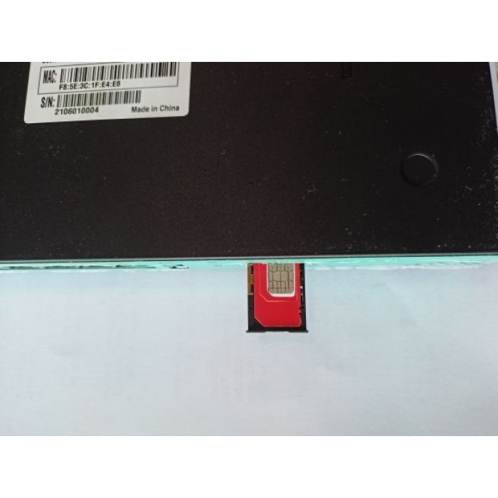
Put a functional SIM card into the SIM slot (please see picture bellow).
Please bear in mind that there are 2 types of antennas: LTE and WiFi. Be sure that you’re putting in the right antenna to the right slot, You can recognize them by female and male connectors.
After ensuring that everything is in the right place, please first connect your LANport then the routers DC interface, please use 12V / 2A power adapter.
Now type into your browsers URL query “192.168.1.1” it’ll take you to the routers firmware
Passwords are: Viper firmware “Password1234” or “admin” for OpenWRT
WiFi default password: Viper firmware “LakeWater561” , in OpenWRT firmware is WiFi without encryption by default.
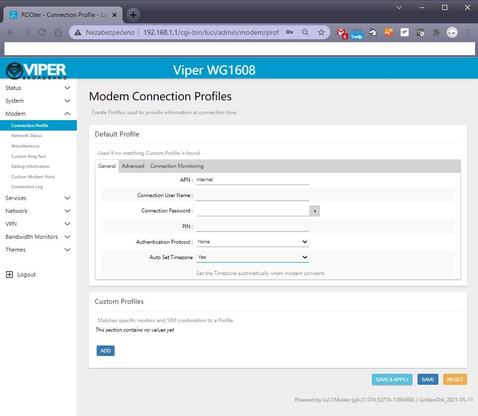
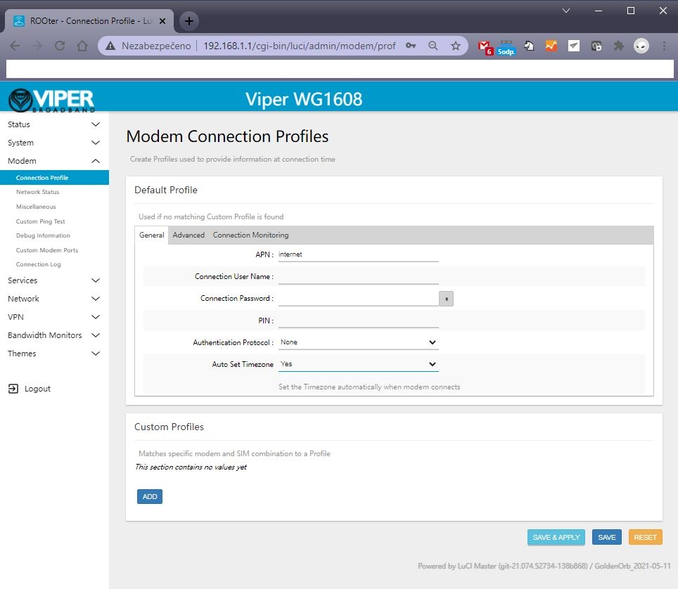
After getting inside your firmware please go to “Modem > Connection profile” and set your APN to “internet” or other APN from your provider and wait at least 5 minutes.
A few of the more common carrier APNs are listed below:
Don’t forget to check “Modem > Network Status” to see if your router recognizes:
Your SIM card
Your modem
Strength of your signal
If you see every mentioned option in No. 6 then congratulations!!! Your router is ready to be deployed. We hope that this user manual was helpful. We’re trying to keep it as simple as humanly possible.
We set customers own specific settings as long as they’re mentioned in the order note.
If you have any more questions, please be sure to contact us at [email protected].
ADVANCED SECTION
QUECTEL RM520N-GL, RM502Q AND OTHER QUECTEL MODULE SETUP IN OPENWRT FIRMARE :
1 – go to the Network – Interfaces – 4G menu and check the 4G/5G module button , then you can set the APN
2 – Then save and reboot and you can see 4G/5G connected in Status page :
Please insert your 4G or 5G LTE card in “M.2 LTE card slot”
Connect your pigtails to your LTE card and your WiFi card (If there’s a right slot for it marked with “WiFi” text)
A) is the correct way.
B) This one isn’t as this may result in damaging contact between the LTE card and antenna.
This tutorial will demonstrate the build and configuration process for the M2M 5G LTE H721 Dual Modem Router.
2023 note : This popular router can support new popular 5G modules like Quectel RM502 Q, RM520N or Sierra Wireless 5G modems. New switch just for Sierra Wireless EM919x and EM7690, these card default work at PICE mode. We add new switch just let EM919x EM769x work at USB mode. Please see this video : https://www.youtube.com/watch?v=whKcn4SFMKQ
1 – New firmware has support AW7916 / AW7915 wifi 6 modules. Do not support QCN wifi 6.
2 – It supports RM520N-GL. X-WRT soft engineer use RM520N . You need manual create new interface (QMAP cellular) and manual choose AT port to display modem signal information
3 – New fw has introduce new Quectel QMAP , it will reduce cpu load.
4 – Full support hw-nat, 5 – Support dual-lte or 5G modem load-balance (see instruction.)
The modem signal Luci is still in development.
Please note, Wodaplug ( 524wifi.com ) are using V7 unique rebuild version of this popular modem for full 5G equiped with protection, pls note – some pictures of older versions may be not coresponding to your newer model. Good new also is that we just finish 5G_NR signal status page and Simcom 8200 5G modem support.
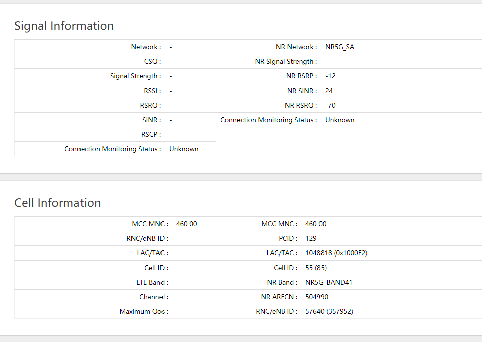
5G Signal information displayed by our router
There are many possible build variations for building the M2M. Autor decided to use a single EM7565 CAT12 M.2 modem and dual mini PCI-E WiFi cards—one for 2.4GHz and the other for 5GHz WiFi.
The WiFi cards used in this build are dual band cards, but each card may only operate on one band at a time—either 2.4GHz or 5GHz. The QCA AC WiFi card will work well for its higher speed capabilities on the 5GHz WiFi, while the Atheros WiFi card will handle the 2.4GHz WiFi. New firmware support Ath10k 802.11AC Wave2, about 20% improvement at Wifi 5.8G support QCA9984 QCA9886 QCA9888
The components used for this particular build are:
(1) Small Phillips Head Screwdriver (1) Small Standard Head Screwdriver (1) 5/16 Nut Driver, Socket or Wrench (1) Wooden Chopstick with Tip Sanded Flat (or similar object to use for connector attachments)
OPENING THE ROUTER CASE:
There are seven screws in total to remove before separating the router case. This is required to obtain access to the router PCB to install the Modem, WiFi Cards and Pigtail connectors.
Place the router on a flat table or surface with the lower case decal facing up.
Remove the three screws along the upper edge.
Remove the two screws from each side of the router.
After removing all seven screws, carefully slide the lower case back about an inch from the upper case.
Hold the lower and upper case in their position and carefully flip the router into its upright position.
Remove the Upper Case from the router assembly to expose the PCB (Printed Circuit Board).
The EM7565 is be mounted in the M.2 interface slot labeled #3
The 5 Volt WiFi Card is to be mounted in the Mini PCI-E interface slot labeled #2 since it supports both 3.3 and 5 Volt WiFi Cards.
The Atheros WiFi Card is to be mounted in the Mini PCI-E interface slot labeled #1
(Note: The M.2 interface slot #4 on the underside of the PCB for a second modem is not being used for this build).
Carefully slide each of the modem and WiFi cards into their proper interface slot—paying special attention to the proper key/pin alignments—and secure each of the cards in place with the screws that are included (shown in the red circles):
INSTALLING THE ANTENNA PIGTAIL CONNECTORS
There are 12 different antenna cutouts and plastic plugs that should accommodate most any antenna configuration. Decide what antenna placements work best for a particular build.
Below is the antenna configuration used for this build which works rather well.
Remove the plastic plugs from both upper and lower case to be used for the antennas.
Place each of the WiFi RP-SMA and Cellular (LTE) SMA antenna pigtail connectors into their proper cutout slot.
Consideration should be given as to the length of cable being used in relation to the location of the WiFi card or modem it will be connected to.
Notice that the SMA and RP-SMA antenna connectors appear similar, but they are different. One is not compatible with the other. Generally, WiFi uses RP-SMA while cellular uses SMA. The differences can be seen on the following image:
Place the star and lock washers over the connector and secure in place with the nut. Use the 5/16 nut driver to snug the connector nut—but do not over-tighten.
Now the modem and WiFi cards are installed and secured in place with their screws, and the pigtail connectors are installed in the upper and lower case, it is time to install the pigtail’s U.FL and MHF4 connectors to the cards.
Care must be exercised when working with these connectors to avoid damaging the tiny connectors or ports on the modem. Good lighting is crucial and a magnifying glass will be extremely useful.
When connecting these connectors, make certain they are flat and aligned perfectly with the connector port of the modem. A flat instrument placed on top of the connector (the wooden chopstick in this example) will help to snap the connector evenly in place.
Do not force the connects. If they do not snap/pop into place with slight downward pressure, chances are the connector and port are not aligned.
Once the connectors are installed, the Selector Switch on the PCB must be set for this particular configuration. According to the documentation, when using the M.2 slot #3 for the modem, and a WiFi Card in the Mini PCI-E slot #1, the Switch should be in the down position:
Switch selector (optional – depends on model – wodaplug.com new V5G version does NOT have switch)
Confirm the switch is in the down position (for older HW versions only):
The Upper and Lower cases may now be reassembled and secured with the seven screws.
The antennas may also be installed in their proper positioning.
CONFIGURING ROUTER WITH GOLDENORB
The M2M NEXG H721 Dual Modem Router comes with GoldenOrb firmware preinstalled which helps to simplify the overall router build and configuration.
Plug the 12 Volt power supply into the power plug on the router.
Connect an Ethernet cable from one of the LAN ports on the router to the Ethernet plug on the PC.
(Note which SIM Card slot will be used for the EM7565 but DO NOT install the SIM Card until after GoldenOrb is configured and ready to connect to the internet).
1. LAN – SIM – Power
Once the M2M router has booted up, open a web browser and enter 192.168.1.1 in the address bar and press enter. The Splash Page should appear. Click on the “Router Login”:
2. Router splash page
Log into the router using the default user name “root” (without the ““marks) and the default password of “admin”.
The default user name and password is located on the decal on the bottom of the router.
Default WiFi passwords – for older firmare version it was “12345678” , new Rooter firmware version use “rooter2017” as default WiFi password.
3. Router Login
Once logged in, the Overview screen should appear.
4. Overview screen
From the left side tabs, select System > System > General Settings.
Use the Time Zone down arrow and select the proper time zone.
Click on the Sync With Browser button.
Click Save and Apply.
(Important, any change in a GoldenOrb setting must be Saved and Applied to implement and remember the change).
5. Time zone
Go to Modem > Connection Profile > General > APN
APN stands for Access Point Name, which is required to identify and connect to a specific cellular carrier. Each carrier uses a different APN.
Type the correct APN used by your cellular carrier that is tied to the SIM Card and plan to be used in the M2M router.
Click on Save & Apply.
A few of the more common carrier APNs are listed below:
Go to System > Administration > Router Password and enter a password that will be used to log into GoldenOrb.
Some may prefer to skip this step and leave the default password of “admin”. This may be changed after all of the other configurations are made and the router is connected to the internet.
7. Setting login password
It is now time to configure the WiFi. Go to Network > Wireless.
The Wireless Overview screen will appear and show the WiFi cards installed in the router. In this build, Radio0 is the Atheros card used for the 2.4GHz WiFi network.
Click on the Radio0 Master tab at the top left of the screen.
8. Select Wireless Network Radio0
Select the Mode and Channel that the 2.4GHz network is to operate on.
In this case, N is selected for the Mode and Channel 11 is used since it has little traffic on that channel.
The Channel can be changed to another channel if the one selected becomes too congested.
There are WiFi analyzer apps that can be downloaded onto your smart phone to assist in selecting the best, non-congested channel available at your location.
Enter the ESSID that the 2.4GHz WiFi Network will be named. In this build TestHome was used.
9. Configure Atheros Radio0 2.4GHz 1
Click on the Wireless Security tab in the lower part of the Interface Configuration screen.
Select the Encryption to be used by selecting the down arrow. In this case WPA2-PSK is selected.
Under Key, enter the Password that will be used to Log onto the 2.4Ghz WiFi Network.
Click Save & Apply to save setting.
Next is to configure the 5GHz WiFi. Go to Network > Wireless and select the Radio1 Master from the top of the menu.
Radio1 is the Complex card used in this build.
11. Select Wireless Network Radio1
Select Mode and Channel that 5Ghz WiFi network is to operate on.
In this case, AC for the Mode and Channel 36 was selected since there is little traffic on this channel. This can be changed to another channel if this one becomes too congested.
Again, a WiFi Analyzer app will help make the proper selection.
Enter the ESSID that the 5GHz WiFi Network will be named. In this case TestHome5G was used.
12. Configure WiFi Radio1 5GHz 1
Click on the Wireless Security tab in the lower part of the Interface Configuration screen.
Select the Encryption to be used by selecting the down arrow. In this case WPA2-PSK is selected.
Under Key, enter the Password that will be used to Log onto the 5Ghz WiFi Network.
Click Save & Apply to save setting.
Default WiFi passwords – for older firmare version it was “12345678” , new Rooter firmware version use “rooter2017” as default WiFi password.
13. 5GHz WiFi Password and Encryption
Optional: For users who may have limits imposed by their carrier on the amount of hotspot data that may be used on a monthly basis, my want to use the TTL custom settings.
Go to Network > Firewall > Custom TTL Settings (top of the screen) > Enable > set to 65 > Save & Apply.
14. TTL Settings
Assuming all of the settings are properly configured, you should now be ready to connect to the internet. Unplug power from the router, install an activated SIM Card, plug the power back in and give it a minute or two to connect.
1 – New firmware has support AW7916 / AW7915 wifi 6 modules. Do not support QCN wifi 6.
2 – It supports RM520N-GL. X-WRT soft engineer use RM520N . You need manual create new interface (QMAP cellular) and manual choose AT port to display modem signal information
3 – New fw has introduce new Quectel QMAP , it will reduce cpu load.
4 – Full support hw-nat, 5 – Support dual-lte or 5G modem load-balance (see instruction.)