Posted on

524WiFi™ Pulse M6E-OUT Pro Plus: Outdoor Wi-Fi 6E Mesh

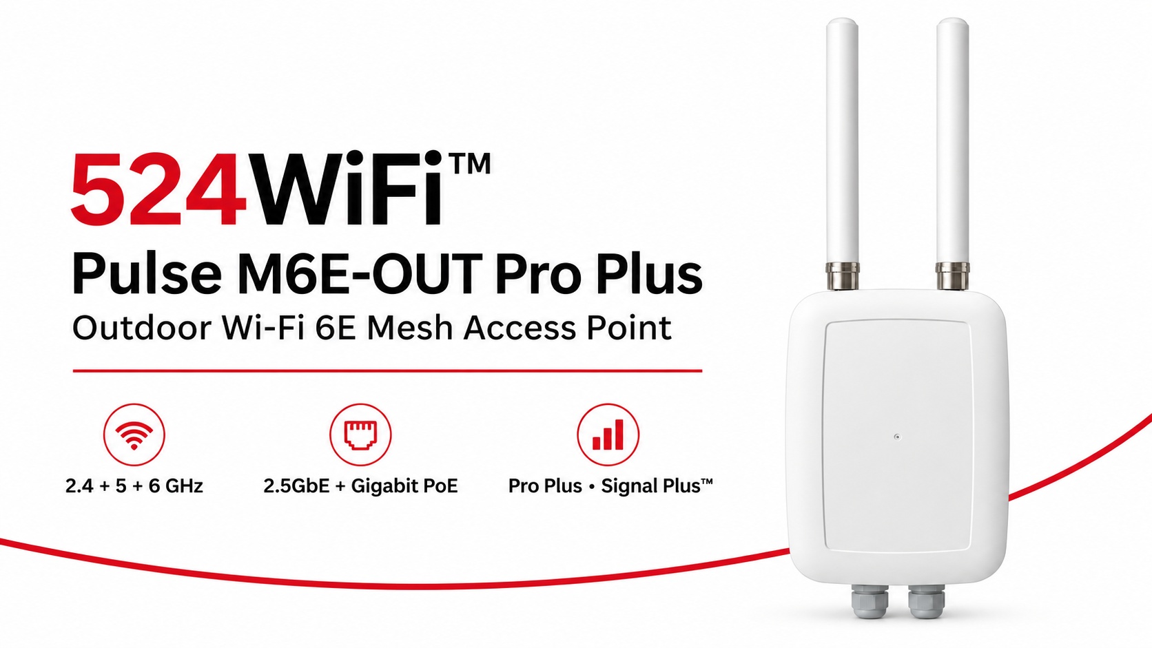
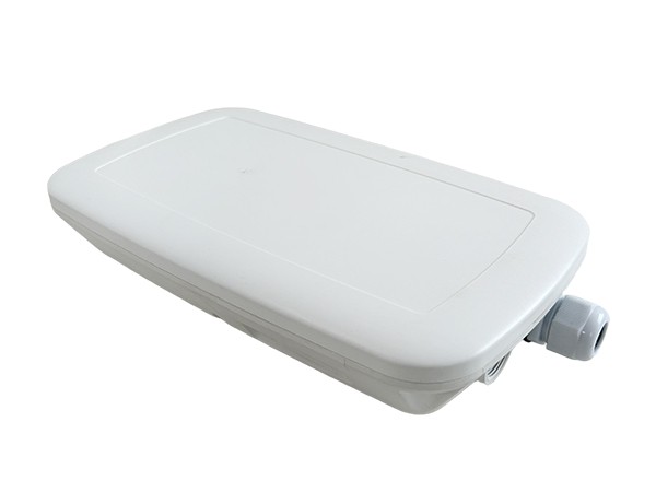
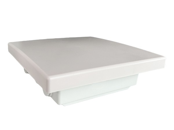
524WiFi™ Pulse M6E-OUT Pro Plus outdoor Wi-Fi 6E mesh access point

524WiFi™ Pulse M6E-OUT Pro Plus brings the radio platform, outdoor enclosure and model-specific antenna assembly together for a professionally planned Wi-Fi 6E mesh installation. Start with a complete fixed network node and build coverage and inter-node links around the working area.

Three radio bands for the complete site network

Independent 2.4, 5 and 6 GHz radios give the installation three concurrent 2×2 radio paths. The Qualcomm IPQ5018 platform combines a dual-core ARM Cortex-A53 processor at 1.0 GHz with 512 MB DDR3L. A 2.5GbE interface supports the wired uplink, while a Gigabit Ethernet interface with PoE provides practical network and power integration.

The published theoretical PHY rates are up to 573 Mb/s at 2.4 GHz and 2,402 Mb/s each at 5 and 6 GHz. Channel widths reach 40 MHz at 2.4 GHz and 160 MHz on the two higher bands. Choose channels and radio roles around client traffic, the mesh topology and the operating country.

An antenna assembly matched to the outdoor node

The assembly combines two external 5 GHz omnidirectional antennas, two internal 2.4 GHz omnidirectional antennas and an internal directional 6 GHz panel serving the two 6 GHz RF paths. Aim the panel toward the intended link and keep its enclosure face clear of metalwork. This lets the installation use directional interconnection and local coverage deliberately.

Pro Plus and Signal Plus™ for deployment

Pro Plus combines our tuned product configuration, model-specific firmware selection and integration support. Signal Plus™ brings antenna placement, polarization, feed losses, radio roles and channel planning into the same RF system. Commission the complete node under the traffic and RF conditions of the actual site.

Fixed mesh nodes and moving clients

Use the M6E-OUT as a fixed outdoor infrastructure node. Pair it with Pulse M6E-IN for indoor infrastructure and Pulse R6-D2-IN or R6-T3-IN roaming clients on moving Ethernet-equipped machinery. Plan compatible firmware, authentication and RF overlap across the route. Mesh interconnection and moving-client roaming serve complementary roles in the complete network.

Explore the 524WiFi™ Pulse M6E-OUT Pro Plus specification and order configuration, or compare the Pulse product family.

Platform reference: DRWave-1000 / DR5018S.

Posted on

Welcome to 524wifi – cruising online for more than 24 years and having 40+ certificates – home of the best WiFi & LTE 5G NR & Internet over Coax & GEPON Passive Optical networks!

Welcome to 524wifi – home of the best WiFi & LTE 5G NR & Internet over Coax & GEPON Passive Optical networks! Certified by UK Joscar Hellios, from automotive for sample by VW group , telecomunications Nokia, for onlne Google certified … and tons of others big companies we have over 40 security clearances and certificates for to sale and for implement into USA and EU and globally.

There is no continent, where we would not have a satisfied customer! Yes, our modules works and we have already delivered our Wi-Fi modules even to Antarctica ! You can find our modules, for example, in wind turbines, drones, ships, trains (Norway, Czech SK and many more),public transportation comm systems, aircrafts, both civil, acrobatic and military… on land, on water and in the air. NASA has also ordered samples, so the next goal is to get them into the outer Space! 524WiFi Pro+ modules! Well if you do someting well for almost 25 years, you have lot of customers…..

With more than 24 years of experience in the Networking Industry, our partners as Wodaplug Quectel & SIMcom, Compex & Wallys communications and lot more. Wodaplug offers reliable solution for Ethernet Data over Coax (EOC), G EPON and 4G 5G LTE routers & backup units.  Quectel leads market in LTE 5G 4G modules & IoT technologies. 524wifi is part of Google Customers Reviews program to assure customers satisfaction – Google Approved. Eshop owner is located in EU – CZ.

If that huge time period we developed ourselves as connecting bridge between modules and chips designers, drivers designers and practical users , industrial aplications

Please, if you are a distributor / dealer or ISP, first create an account and mail us for business login with discount. For support write email to sup..

For News questions and Promo – pleasae visit and follow as on our 524WiFi Facebook!

Qualcomm Atheros & MEDIATEK reference design miniPCIe Wi-Fi modules with best parameters,

We do HELP customers DEVELOP ath11k for DR9074 WIFI 6 and WIFI 7 ath12k driver cards

Quectel LTE 4G / 5G Sub 6G cellular modules – EC25, EG25-G, EP06, EM060K, EM12-G, EM160R, RM502Q, RM510Q, RM520N …

We can deliver all Quectel, SIMCOM, TELIT, SIERRA WIRELES, SPARKLAN and other wireless modules and antennas for your business projects, please ask us!

New Wodaplug Dual Mode XPON ONU for GPON and GEPON in one device !

Internet over coax cables for long range and with more than 300Mbps – Wodaplug EOC series

Check Wodaplug dual SIM 4G / 5G LTE routers with ROOTer and X WRT firmware!
Posted on

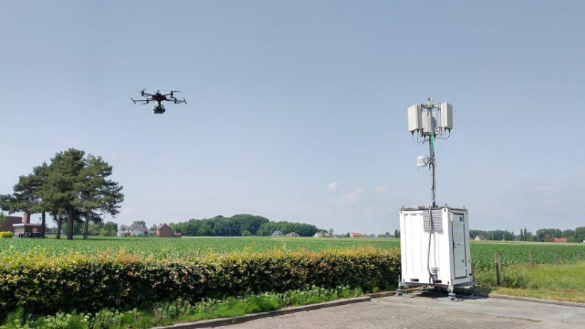
Long-Range Drone Video & Control Links: Choosing Between DR5322, DR9574S, and DR5424

For agricultural, inspection, and mapping drones, the weakest link in the field is rarely the flight controller — it’s the wireless link. Video dropouts, control-command latency, and interference between multiple concurrent aircraft all directly affect operational efficiency and, in some cases, flight safety. Picking the right wireless hardware platform ultimately comes down to trade-offs between throughput, range, integration approach, and deployment environment.

524WiFi and Wallys currently offer three Qualcomm WiFi 7-based platforms that map to different drone video/control link scenarios: DR5322, DR9574S, and DR5424. Here’s how they differ, and which one fits which use case.

DR5322: Lightweight and modular, built for cost-sensitive edge nodes

The DR5322 is built on Qualcomm’s IPQ5322 (quad-core Cortex-A53 @1.5GHz) and is essentially a compact routerboard: onboard 2×2 2.4GHz radio, with 5GHz/6GHz handled through an add-on QCN9274/QCN6274 WiFi 7 module, reaching up to roughly 5764Mbps physical data rate. It offers 4x 2.5G Ethernet ports plus 1x 10G SFP, with 802.3bt PoE support.

This “onboard 2.4G + pluggable high-band module” architecture makes the DR5322 well suited as a relay node or video-transmission hub for a single small multirotor — where the priority is small footprint, low power, and controlled cost rather than maximum throughput. Think field-deployable relay boxes or vehicle-mounted repeaters.

DR9574S: The modular flagship, built for relay towers and multi-drone coordination

The DR9574S runs on Qualcomm’s IPQ9574 (quad-core ARM-A73 @2.2GHz) and is the most configurable of the three — six version options (2×2/4×4, 5G/6G/5-7G) let you tailor the band mix to the project. It supports OFDMA, MU-MIMO, and multi-link operation (MLO), with 10G SFP, 10G Ethernet with PoE, and 2 Gigabit ports, plus optional GPS. Industrial-grade design supports operation from -20°C to 70°C.

This configuration is a better fit for fixed base stations, relay towers, or scenarios that need to manage video/control links for multiple drones at once — for example, a large-scale agricultural operation running several spraying drones simultaneously, where the ground station needs to reliably carry multiple concurrent video and control streams.

DR5424: High-throughput tri-band, built for aggregating high-definition multi-stream video

The DR5424 is the most integrated of the three: Qualcomm IPQ5424 (quad-core Cortex-A55 @1.8GHz), full onboard tri-band WiFi 7 (4×4 MU-MIMO), 320MHz channel width, with theoretical physical data rates up to 1376Mbps on 2.4GHz, 8647Mbps on 5GHz, and 11530Mbps on 6GHz. It also carries the strongest port configuration of the three: 4x 2.5G plus 2x 10G Ethernet.

One important clarification: DR5424’s tri-band design is switchable, not concurrent — the three bands are there to be switched between as needed to avoid interference, not to simultaneously carry separate traffic types (e.g., control on one band, video on another, backhaul on a third). This distinction matters when evaluating a project’s actual concurrent multi-video-stream capacity.

With onboard tri-band radios and multiple high-speed Ethernet ports, the DR5424 is well suited as an aggregation gateway for high-definition, multi-channel video feeds — for example, when several aerial video streams need to be backhauled simultaneously to a ground station for real-time stitching or AI-based analysis.

Side-by-side comparison

DR5322 DR9574S DR5424 Chipset IPQ5322 (A53 @1.5GHz) IPQ9574 (A73 @2.2GHz) IPQ5424 (A55 @1.8GHz) Radio architecture Onboard 2.4G + pluggable 5/6G module Modular, 6 version options (2×2/4×4) Full onboard tri-band, 4×4 Max theoretical rate ~5764Mbps ~5765Mbps (per radio) ~11530Mbps (6GHz) Channel width — Up to 160MHz Up to 320MHz Ethernet 4x 2.5G + 1x 10G SFP 2x 1G + 1x 10G+PoE + 1x 10G SFP 4x 2.5G + 2x 10G GPS No Optional No Typical use case Lightweight relay node / cost-sensitive projects Fixed base station / multi-drone relay tower High-definition multi-stream aggregation gateway

Which one should you choose?

  • Budget-constrained projects that only need to support a single drone or a small number of video links — a lightweight relay node: go with DR5322.
  • Larger operational radius, managing multiple drones online at once, needing a fixed base station or relay tower: go with DR9574S, selecting the version that matches your band requirements.
  • Concurrent high-definition multi-stream video backhaul with high Ethernet aggregation bandwidth requirements, needing an edge gateway: go with DR5424.

All three platforms support OEM/ODM customization, including long-range transmission software tuning, antenna selection, and enclosure design. If you’re evaluating wireless hardware for a drone video/control link project, reach out to info at 524wifi.net or 524wifi.com for selection guidance or to request samples.

Posted on

Tuning TDMA Scheduling for a Multi-Station PtMP Deployment: A Field Case

A recent PtMP deployment we worked on had a familiar problem: the hardware checked every box on paper — right frequency band, right range, right radio — but once more than a handful of remote stations came online, performance got uneven. Some stations ran fine. Others lagged, dropped packets under load, or just underperformed relative to what the spec sheet promised.

The instinct in situations like this is usually to blame the radio hardware. In our experience, the actual bottleneck is almost always the scheduling layer — how airtime gets allocated across stations, not the raw RF performance.

Article content

What we found

Standard TDMA firmware implementations often use static or near-static slot allocation — every remote station gets a roughly equal time slice, regardless of what that station actually needs or how far it is from the base station. That works fine at low station counts. It breaks down as deployments scale, because distance, interference, and per-station data demand aren’t equal across a real network — a fixed schedule fights the physical reality it’s trying to serve.

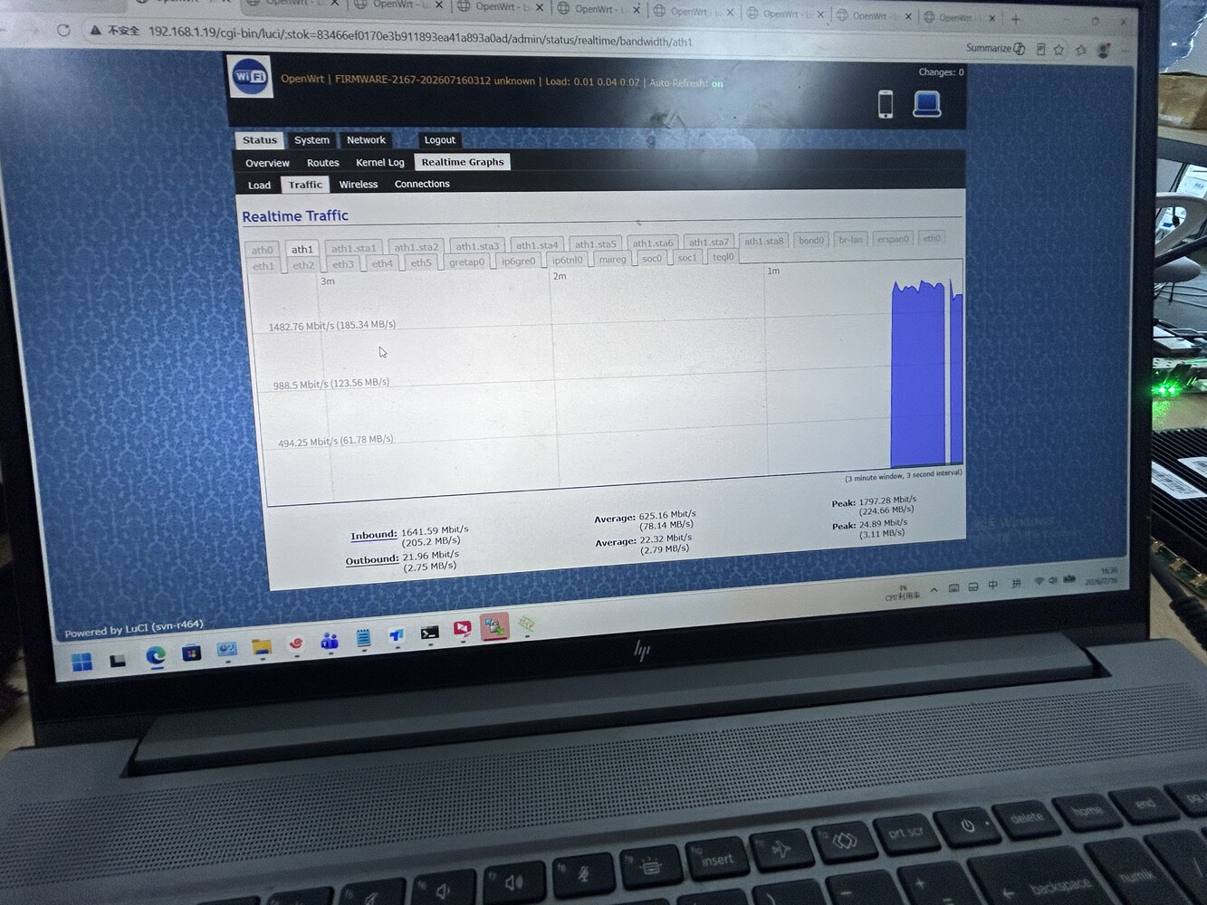
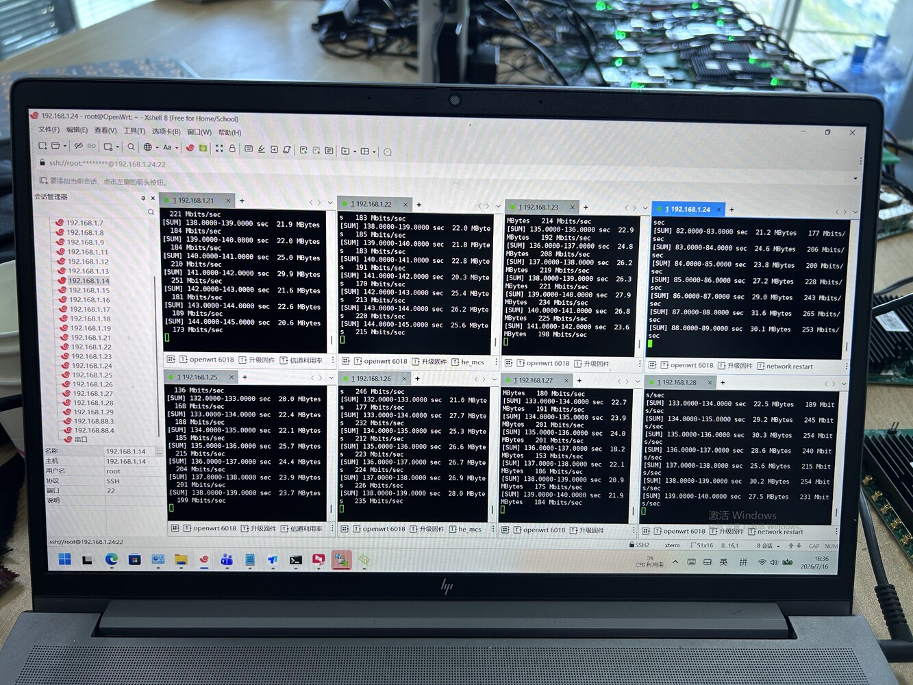
We rebuilt the scheduling logic on the firmware side to allocate airtime dynamically — closer to a priority/demand-weighted model than a fixed round-robin — and re-ran the same deployment topology: 8 remote stations, one base station, downlink test, same OpenWrt-based platform.

Result: per-station throughput of 130–265 Mbit/s, aggregate peak of 1,797.28 Mbit/s, aggregate average of 625.16 Mbit/s — with the spread between best- and worst-performing stations narrowing noticeably compared to the default static-scheduling baseline.

Article content

Why this matters beyond one deployment

The hardware didn’t change. The module, the antenna, the base station — none of it changed. What changed was the software layer managing how that hardware gets used across multiple simultaneous stations. That’s usually the part vendors don’t customize, because it means going deeper than swapping a chipset or bumping a spec sheet number.

This is also where we think there’s room for more collaboration than the industry typically does. A lot of teams building PtMP or multi-node wireless products — robotics, drones, distributed sensor networks — have strong hardware instincts but limited bandwidth to go deep on scheduling firmware, OpenWrt customization, or protocol-level tuning. That’s specifically the kind of work we do on the software side, independent of whether the hardware itself comes from us.

If your team has a multi-station deployment that’s hitting a similar wall — good radios, uneven real-world performance — we’re happy to compare notes, or scope what a scheduling-level fix would look like for your specific topology.

Posted on

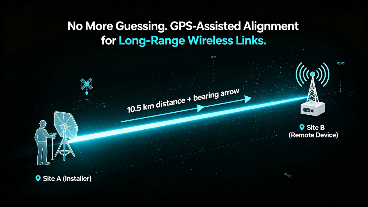
GPS Smart Deployment for Long-Range WiFi PtP: What If Your AP Could Tell You Where to Point?

Deploying long-range wireless links has always been a field engineering challenge.

For a Point-to-Point (PtP) wireless connection, performance depends heavily on antenna alignment.

A few degrees of misalignment can mean:

  • Lower throughput
  • Reduced link stability
  • Poor signal quality
  • More time spent on-site troubleshooting

Traditionally, engineers need to rely on:

  • GPS devices
  • Maps
  • Compass tools
  • Signal strength monitoring
  • Multiple technicians communicating between two locations

But what if the wireless device itself could help you find the right direction?


From GPS Location to Smart Alignment

Imagine this:

You install an AP at the local site.

After powering it on:

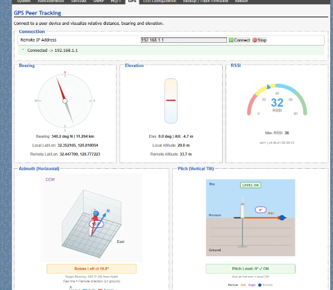
  1. The device automatically obtains its GPS coordinates.
  2. The remote site device shares its location information.
  3. The web interface calculates the optimal alignment direction.
  4. The system provides recommended:
  • Horizontal rotation angle (Azimuth)
  • Vertical tilt angle (Elevation)

Instead of asking:

“Which direction should I point this antenna?”

The system tells you:

“Rotate 127.5° horizontally and tilt 8.3° upward.”


Simplifying Long-Distance Wireless Deployment

For outdoor wireless networks, especially:

  • WISP networks
  • Rural broadband
  • Industrial campuses
  • Mining sites
  • Smart agriculture
  • Remote monitoring systems

deployment efficiency is critical.

GPS-assisted alignment can help engineers:

✅ Reduce installation time

✅ Minimize alignment errors

✅ Improve first-time connection success rate

✅ Simplify remote deployment and maintenance


How It Works

A GPS-enabled wireless platform combines:

1. Location Awareness

Each device knows its own:

  • Latitude
  • Longitude
  • Position information

2. Remote Device Coordination

The AP exchanges location data with the remote endpoint.

3. Direction Calculation

Based on two GPS points, the system calculates:

  • Distance between sites
  • Direction angle
  • Antenna pointing recommendation

4. Web-Based Guidance

Engineers can view the recommended installation angle directly through the device management interface.

Article content

No additional measurement tools required.


Designed for Next-Generation Outdoor Connectivity

524WiFi and Wallys have integrated GPS capability into selected industrial wireless platforms, including:

524WiFI WiFi 6 Long Range Kit

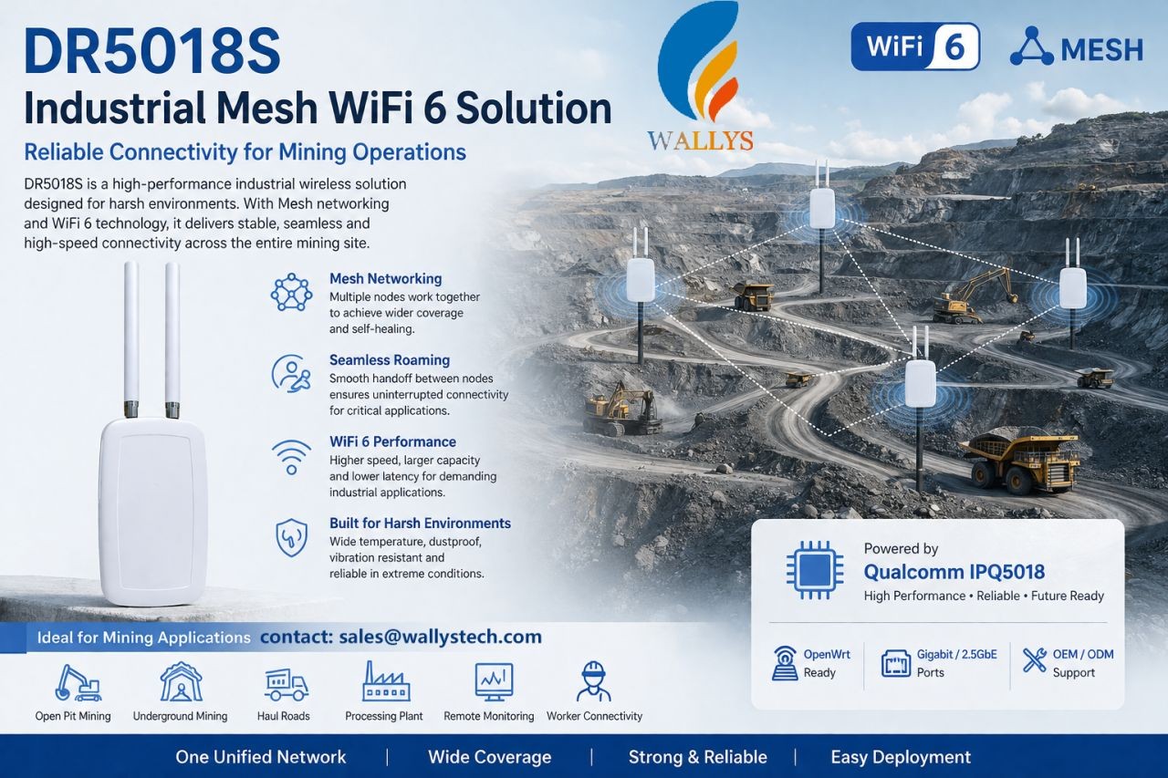
DRWAVE-1000 Built around Qualcomm IPQ5018 platform, designed for industrial networking applications requiring reliable wireless connectivity.

Article content

524WiFi WiFi 7 Long Range Kit

Powered by Qualcomm IPQ9574, supporting next-generation high-performance wireless applications.

Article content

With GPS integration, these platforms enable smarter deployment possibilities for long-range wireless networks.

Posted on

The Hidden Challenge in Robot Fleets: Roaming, Latency, and Wireless Stability

When people talk about autonomous robots, the conversation usually focuses on AI models, sensors, cameras, and navigation algorithms.

But there is another critical layer that often determines whether a robot system succeeds in real-world deployment:

Wireless connectivity.

A robot can have advanced AI capabilities, but without reliable communication, even the smartest robot may struggle in a dynamic industrial environment.

For large-scale robot fleets, connectivity is no longer just a networking feature. It becomes part of the robot’s operational reliability.

The Reality of Wireless Challenges in Robot Deployments

In warehouses, factories, farms, and outdoor industrial environments, robots are constantly moving.

An AMR (Autonomous Mobile Robot), for example, may need to:

  • Move across different areas with changing RF conditions
  • Maintain real-time communication with control systems
  • Upload high-resolution camera data
  • Receive navigation and task instructions
  • Coordinate with other robots in the same environment

During these operations, wireless networks face several challenges:

1. Roaming: Staying Connected While Moving

A robot moving through a large facility often needs to transition between multiple access points.

A poor roaming experience can cause:

  • Packet loss
  • Video interruption
  • Control delays
  • Temporary disconnection

For industrial robots, even a short communication interruption can affect efficiency and safety.

Advanced roaming mechanisms such as 802.11k/v/r help devices make faster and smarter roaming decisions by improving network awareness and reducing handover time.

However, successful roaming also depends on:

  • Proper RF planning
  • AP deployment strategy
  • Client behavior optimization
  • Network management

2. Latency: Every Millisecond Matters

Many industrial robot applications require real-time communication.

Examples include:

  • Remote monitoring
  • Vision-based inspection
  • Autonomous navigation
  • Robot fleet coordination

High latency can impact:

  • Motion control
  • Response time
  • Task execution efficiency

The challenge is not only achieving high throughput.

A network can provide high speed but still suffer from unstable latency due to:

  • Network congestion
  • Interference
  • Poor link quality
  • Inefficient routing

Reliable industrial wireless networks need predictable performance, not just peak speed.

3. Wireless Stability in Complex Environments

Industrial environments are very different from homes or offices.

Factories and outdoor deployments may include:

  • Metal structures causing reflections
  • Moving equipment blocking signals
  • Multiple wireless networks creating interference
  • Large numbers of connected devices

A robot fleet may experience changing wireless conditions every moment.

This requires networks that can adapt dynamically.

Important capabilities include:

  • Intelligent channel management
  • Interference detection
  • Dynamic path optimization
  • Mesh networking
  • Traffic prioritization

Why Traditional Wi-Fi Approaches Are Not Always Enough

A standard Wi-Fi deployment may work well for static users.

However, robot fleets introduce new requirements:

  • Mobility
  • High device density
  • Continuous connectivity
  • Low latency
  • Reliable uplink performance

The network needs to be designed around the robots’ movement and operational workflow.

Building the Wireless Foundation for Next-Generation Robots

The future of autonomous systems will depend on the combination of:

AI + Robotics + Reliable Connectivity

Advanced wireless technologies such as Wi-Fi 6 and Wi-Fi 7 bring important improvements:

  • Higher capacity
  • Better multi-device performance
  • Lower latency
  • Multi-band operation with MLO
  • Improved reliability in demanding environments

But technology alone is not enough.

Successful industrial deployments require:

  • The right wireless architecture
  • Proper RF optimization
  • Reliable hardware platforms
  • Long-term firmware support
  • Real-world validation

Final Thoughts

Autonomous robots are becoming smarter every day.

But intelligence alone does not guarantee successful deployment.

Behind every reliable robot fleet is a reliable communication infrastructure.

The next generation of industrial automation will not only depend on better AI algorithms — it will depend on wireless networks that can keep robots connected, responsive, and operational in the real world.

Reliable connectivity is the foundation that allows autonomous robots to truly become autonomous.

Posted on

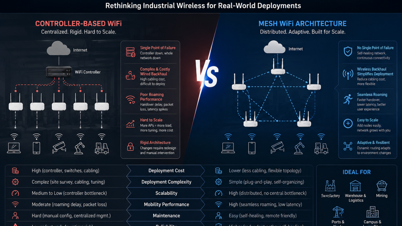
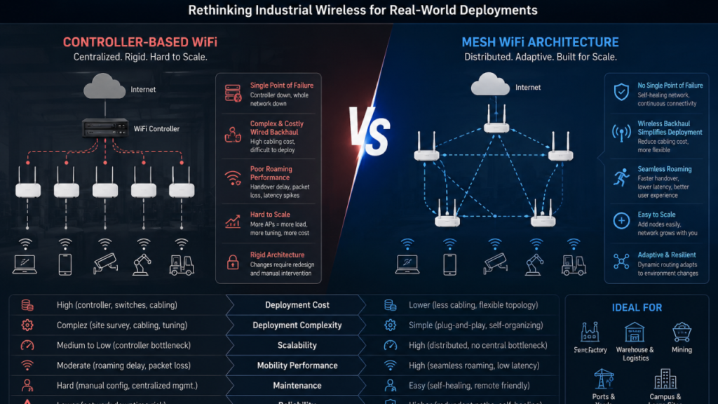
Why Controller-Based Industrial WiFi Is Breaking in Real Deployments

Most industrial WiFi networks are still built on a controller-based architecture.

And in controlled lab environments, it works.

But in real industrial deployments, the story is very different.

Factories, mines, ports, and warehouses are not static environments. They are dynamic, noisy, and constantly changing systems.

And that’s exactly where controller-based WiFi starts to fail.


The Hidden Assumption Behind Controller WiFi

Traditional enterprise WiFi is built on one assumption:

A centralized controller can efficiently manage the entire network.

That assumption only holds when the environment is predictable.

Industrial environments are not.

Once you scale into real deployment scenarios, WiFi becomes less about “AP management” and more about:

  • mobility
  • interference
  • topology changes
  • real-time traffic behavior

And centralized control starts becoming a limitation rather than an advantage.


Where Controller-Based WiFi Fails in Practice

1. Roaming is still not truly seamless

Even with controller-based optimization:

  • handover delay still exists
  • packet loss happens during movement
  • latency spikes under load are unavoidable

This is especially critical for AGVs, mobile robots, and real-time monitoring systems.


2. Wired backhaul limits deployment flexibility

Controller-based architectures heavily depend on wired infrastructure.

But industrial sites are:

  • expensive to cable
  • frequently reconfigured
  • physically difficult to retrofit

This creates a gap between “ideal network design” and “real deployment reality”.


3. Scaling introduces complexity, not simplicity

Adding more APs does not mean linear scalability.

Instead, it introduces:

  • higher controller load
  • complex RF planning
  • continuous tuning effort
  • increased operational cost

At scale, the network becomes harder to manage, not easier.


4. Centralized failure domains are too rigid

In controller-based systems:

  • architecture is tightly coupled
  • dependencies are centralized
  • failure impact can cascade

A small issue can affect a disproportionately large part of the network.


Why Mesh Architecture Is Gaining Real Adoption

Mesh WiFi is not new—but industrial requirements are forcing a structural shift.

Instead of forcing traffic through a central controller, Mesh builds a distributed network where nodes collaborate dynamically.

Key advantages include:

Distributed control

No single point of dependency for network decisions.

Self-healing topology

Traffic dynamically adapts when nodes fail or conditions change.

Flexible expansion

New nodes can be added without redesigning the entire system.

This aligns far better with how industrial environments actually evolve.


Important Reality Check: Mesh Is Not a Silver Bullet

Mesh does NOT eliminate RF physics.

In real deployments, you still need to consider:

  • interference in industrial environments
  • bandwidth sharing between backhaul and access
  • multi-hop latency trade-offs
  • proper RF planning

But the key difference is:

Mesh adapts to real-world constraints instead of fighting against them.


The Real Shift in Industrial WiFi

This is not a feature comparison between Mesh and Controller WiFi.

It is a structural shift in architecture thinking:

  • From centralized control → distributed intelligence
  • From static topology → adaptive topology
  • From planned deployments → evolving networks

Industrial WiFi is no longer about perfect design.

It is about surviving real-world complexity.


Final Thought

Controller-based WiFi still works in controlled enterprise environments like offices and campuses.

But in industrial deployments, the question is no longer:

“How powerful is your controller?”

It becomes:

“Why are you still forcing a centralized architecture into a distributed environment?”


If you are building industrial networking products…

If you are currently working on:

  • Industrial routers
  • Mesh WiFi systems
  • OEM/ODM networking platforms
  • Edge connectivity devices
  • WiFi solutions for AGVs, robotics, or smart factories

and are facing challenges such as roaming instability, deployment complexity, or scalability limitations—

We can share practical architecture insights based on real-world industrial WiFi deployments, including Qualcomm-based WiFi 6 Mesh platform designs.

Feel free to connect or message me to discuss your project.

Article content
Posted on

From NVIDIA Jetson Development Kit to Production: What Robotics Companies Need to Consider Beyond AI Computing

For many robotics companies, the NVIDIA Jetson Development Kit is the first step when building a new product.

It allows engineers to quickly evaluate system concepts, connect peripherals, test software, and verify whether the hardware platform can support their application.

However, after the prototype stage, many teams face a different challenge:

The development kit is not the final product.

A development board is designed for flexibility and evaluation.

A commercial product needs to be designed for:

  • Specific mechanical dimensions
  • Required interfaces
  • Stable power supply
  • Thermal conditions
  • Manufacturing process
  • Long-term availability

This transition from evaluation platform to production hardware is where many engineering teams start facing challenges.

The question changes from:

“Can we make the prototype work?”

to:

“Can we build thousands of units with consistent quality?”


Development Kit Is Only the Beginning

A Jetson Development Kit is an excellent engineering tool.

It helps teams quickly verify:

  • Processor performance
  • Camera connection
  • Sensor integration
  • Software environment
  • Application functionality

During early development, engineers usually focus on functionality.

They may connect:

  • USB cameras
  • External sensors
  • Network devices
  • Additional modules

Everything works on the lab desk.

But when moving into a real product, these temporary solutions often become limitations.

A production device cannot simply place a development kit inside an enclosure.


What Changes When Moving to Production?

1. The hardware needs to fit the product

One of the first challenges is mechanical integration.

A development kit has fixed:

  • Size
  • Connector locations
  • Mounting structure

But the final product may have strict requirements.

For example:

A mobile robot may need all electronics installed inside a compact chassis.

An industrial inspection device may require a specific enclosure.

A customized carrier board allows engineers to redesign the hardware around the actual product.


2. Interfaces need to match the application

Different products require different hardware configurations.

A development kit provides general interfaces.

A production system often needs customized combinations.

Examples:

  • Multiple camera inputs
  • Ethernet ports
  • CAN interface
  • RS232/RS485
  • GPIO control
  • Sensor interfaces
  • Storage expansion

Instead of adding external conversion boards, a custom carrier board can integrate the required functions directly.

This reduces:

  • System complexity
  • Cable connections
  • Assembly difficulty

3. Power design becomes more important

Power is often underestimated during prototype development.

A desktop environment provides stable power.

A production device has different conditions.

Engineers need to consider:

  • Input voltage range
  • Power distribution
  • Protection circuits
  • Power consumption
  • Startup sequence

For industrial products, unstable power design can create reliability problems that are difficult to diagnose.


4. Thermal design cannot be ignored

Higher computing performance also creates thermal challenges.

During prototype testing, engineers may use:

  • Open-air environments
  • Standard heatsinks
  • Development accessories

Production products require:

  • Designed heat dissipation
  • Enclosure consideration
  • Long-term operating stability

Thermal design needs to happen together with mechanical design.


Common Challenges During Custom Board Development

Based on our experience working on embedded hardware projects, several challenges appear frequently.

Challenge 1:

Prototype works, but the design is difficult to manufacture

A prototype may use:

  • Evaluation boards
  • Additional modules
  • Manual wiring

This is acceptable for engineering verification.

However, mass production requires:

  • Optimized PCB design
  • Simplified assembly
  • Stable component sourcing
  • Manufacturing testing

The production design needs to consider the entire lifecycle.


Challenge 2:

Balancing performance and cost

The highest specification is not always the best product design.

Engineers need to balance:

  • Computing requirements
  • Hardware cost
  • Power consumption
  • Manufacturing complexity

The right design depends on the application.


Challenge 3:

From prototype samples to stable production

A few working prototypes do not mean the product is ready.

Before production, companies usually need to complete:

  • Hardware verification
  • Reliability testing
  • Manufacturing validation
  • Quality control process

This stage requires cooperation between engineering and manufacturing teams.


Key Considerations When Designing a Jetson Production Platform

1. Start hardware planning early

Many companies first focus on software development.

However, hardware decisions made later can affect:

  • Product size
  • Cost
  • Schedule
  • Manufacturing

Early hardware planning can reduce redesign cycles.


2. Select the right development partner

A production hardware project involves multiple disciplines:

  • Hardware design
  • PCB layout
  • Embedded software
  • Testing
  • Manufacturing

A partner with both engineering and production experience can help shorten the transition.


3. Think about future product versions

A good hardware platform should consider future needs:

  • Interface expansion
  • Component availability
  • Product upgrades

The first production design often becomes the foundation for future products.


524WiFi Perspective

At 524WiFi and Wallys, we have been involved in embedded communication hardware development since 2005.

Our engineering capabilities include:

  • Hardware design
  • PCB development
  • Embedded system integration
  • Prototype validation
  • Production support
  • OEM/ODM/JDM services

With the increasing adoption of NVIDIA Jetson platforms in industrial applications, we are expanding our hardware development capability to support companies that need customized Jetson-based platforms.

Our focus is not only building a prototype board.

It is helping engineering teams move from:

Concept → Prototype → Production

through practical hardware design and manufacturing experience.


Conclusion

The NVIDIA Jetson Development Kit provides engineers with a fast way to start development.

But successful products require much more than selecting a computing module.

The transition to production requires careful consideration of:

  • Hardware customization
  • Interface design
  • Power management
  • Thermal solution
  • Manufacturing requirements

For robotics and industrial equipment companies, the biggest challenge is often not proving that the technology works.

It is turning a working prototype into a reliable product.

What challenges have you experienced when moving from development boards to production hardware?

Posted on

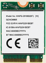
Sparklan WNFQ-291BEI BT

The Sparklan WNFQ-291BEI(BT) is everything a Wi-Fi enthusiast could ask for in a M.2 2230 key E format. Based on the Qualcomm Fastconnect 7800 platform, it comes with support for all the latest Wi-Fi 7 features, Bluetooth, a true industrial package and a highly capable Soft AP mode. If you’re looking for a solution that has it all – this is it.

WNFQ-291BEI

802.11be/ax/ac/a/b/g/n  Industrial Capable Tri-band WiFi Combo, M.2 2230 (E KEY) Module (WiFi 7), Qualcomm, 2T2R

Chipset: Qualcomm WCN7851 , Samples available for orders now.

  • Antenna: 2 x IPEX MHF4 connectors, 2T2R
  • Interface: PCIe: WLAN / USB
  • Supports Dual-Band Dual Concurrent Design
  • Support: Win11/Linux (Open Source) (TBD)

Categories: E Key, M.2Tags: 11be, 2T2R, Industrial Grade, Wifi 7

WNFQ-291BEI, first Qualcomm based WiFi-7 (802.11be) module in M.2 2230 E key formfactor, running PCIe (Wifi) and USB, supports DBDC (Dual-band, Dual-concurrent) mode, but with Tri-band capability (2.4GHz, 5GHz, and 6GHz). WNFQ-291BEI is able to concurrently run 2.4GHz with 5GHz, or 6GHz, and support full IEEE802.11 be/ax/ac/a/b/g/n protocol, up to 320MHz mode.

WNFQ-291BEI designed with 2 spatial streams (2T2R, or 2×2) in MU-MIMO mode. With a standard M.2 E key 2230 formfactor, WNFQ-291BEI can accommodate to all existing platform that has M.2 Adaptor pre-integrated, no extra work with platform design.

Software wise WNFQ-291BEI support Windows, with Linux (Open Source) in the near future. The module is capable to run on both x86 platform and ARM based platform, and supports STA mode and Soft AP Mode*, recommend to run on application includes: digital signage/POS, rugged computer / tablets, fanless automation PC and other industrial environment applications that requires high speed data transmission.

Applications include IPC/ Advertising machine/ OTT/ IPTV/ DVB/ STB / DV/ Mini Driving Recorder/ Intelligent Projector Pico/ VR/ AR terminal/ POS machine/ Vehicle mounted front/ Rear Terminal UAV/ Robot/ Intelligent Gateway/ Smart city and other electronic products.

ROHSReach
STANDARD
WI-FIIEEE 802.11be/ax/ac/a/b/g/n
ChipsetQualcomm WCN7851
Host InterfaceWLAN : PCIe / USB
RADIO
Antenna2 x IPEX MHF4 connectors
Operating Frequency802.11be/ax/ac/a/b/g/n ISM Band
2.400GHz~2.4835GHz5.150GHz~5.850GHz5.925GHz~7.125GHz*Subject to local regulations
MODULATIONS
802.11bDSSS (DBPSK, DQPSK, CCK)
802.11gOFDM (BPSK, QPSK, 16-QAM, 64-QAM)
802.11nOFDM (BPSK, QPSK, 16-QAM, 64-QAM)
802.11aOFDM (BPSK, QPSK, 16-QAM, 64-QAM)
802.11acOFDM (BPSK, QPSK, 16-QAM, 64-QAM, 256-QAM)
802.11axOFDMA (BPSK, QPSK, 16-QAM, 64-QAM, 256-QAM, 1024-QAM, 4096-QAM)
802.11beOFDMA (BPSK, QPSK, 16-QAM, 64-QAM, 256-QAM, 1024-QAM, 4096-QAM)
POWER & SENSITIVITY
WiFiPower – TX (± 2dBm)Sensitivity – RX
11b @ 11Mbps18 dBm≤ -91 dBm (TBD)
11g @ 54Mbps16 dBm≤ -77.5 dBm (TBD)
11gn HT20 @ MCS 716 dBm≤ -76.5 dBm (TBD)
11gn HT40 @ MCS 716 dBm≤ -74 dBm (TBD)
11a @ 54Mbps13 dBm≤ -76.5 dBm (TBD)
11an HT20 @ MCS 711.5 dBm≤ -76 dBm (TBD)
11an HT40 @ MCS 711 dBm≤ -73.5 dBm (TBD)
11ac VHT80 @ MCS 99.5 dBm≤ -64 dBm (TBD)
11ac VHT160 @ MCS 99.5 dBm≤ -62 dBm (TBD)
11ax 2.4GHz
11ax HE40 @ MCS 1112.5 dBm≤ -62 dBm (TBD)
11ax 5GHz
11ax HE20 @ MCS 119 dBm≤ -64 dBm (TBD)
11ax HE40 @ MCS 119 dBm≤ -61.5 dBm (TBD)
11ax HE80 @ MCS 119 dBm≤ -58.5 dBm (TBD)
11ax HE160 @ MCS 119 dBm≤ -55.5 dBm (TBD)
11ax 6GHz
11ax HE20 @ MCS 119 dBm≤ -63 dBm (TBD)
11ax HE40 @ MCS 119 dBm≤ -60.5 dBm (TBD)
11ax HE80 @ MCS 119 dBm≤ -57.5 dBm (TBD)
11ax HE160 @ MCS 119 dBm≤ -54.5 dBm (TBD)
11be 2.4GHz
11be EHT40 @ MCS 1311.5 dBm≤ -62 dBm (TBD)
11be 5GHz
11be EHT20 @ MCS 138.5 dBm≤ -64 dBm (TBD)
11be EHT40 @ MCS 138.5 dBm≤ -61.5 dBm (TBD)
11be EHT80 @ MCS 138.5 dBm≤ -58.5 dBm (TBD)
11be EHT160 @ MCS 138.5 dBm≤ -55.5 dBm (TBD)
11be 6GHz
11be EHT20 @ MCS 138.5 dBm≤ -63 dBm (TBD)
11be EHT40 @ MCS 138.5 dBm≤ -60.5 dBm (TBD)
11be EHT80 @ MCS 138.5 dBm≤ -57.5 dBm (TBD)
11ax EHT160 @ MCS 138.5 dBm≤ -54.5 dBm (TBD)
11be EHT320 @ MCS 137.5 dBm≤ -54.5 dBm (TBD)
POWER CONSUMPTION(TBD)
Continue TXTBD mA (MAX)
Continue RXTBD mA (MAX)
ENVIRONMENTAL
Operating VoltageDC 3.3V
Temperature Range-40~ +85°C (Operating) (TBD)-45 ~ 90°C (Storing) (TBD)
Humidity (Non-Condensing)5 ~ 90% (Operating)5 ~ 90% (Storing)
SIZE
Dimension (MM)30mm (±0.15mm) x 22mm (±0.15mm) x  mm (±0.3mm) (TBD)
Weight3.2g (TBD)
SOFTWARE
Driver (MM)Win 11/ Linux (Open Source) (TBD)
SecurityWPS2.0, WAPI, WPA, WPA2, WPA3
Miscellaneous
Warranty12 Month
HS Code8517620050