Welcome to 524wifi – home of the best WiFi & LTE 5G NR & Internet over Coax & GEPON Passive Optical networks! Certified by UK Joscar Hellios, from automotive for sample by VW group , telecomunications Nokia, for onlne Google certified … and tons of others big companies we have over 40 security clearances and certificates for to sale and for implement into USA and EU and globally.
There is no continent, where we would not have a satisfied customer! Yes, our modules works and we have already delivered our Wi-Fi modules even to Antarctica ! You can find our modules, for example, in wind turbines, drones, ships, trains (Norway, Czech SK and many more),public transportation comm systems, aircrafts, both civil, acrobatic and military… on land, on water and in the air. NASA has also ordered samples, so the next goal is to get them into the outer Space! 524WiFi Pro+ modules! Well if you do someting well for almost 25 years, you have lot of customers…..
With more than 24 years of experience in the Networking Industry, our partners as Wodaplug Quectel & SIMcom, Compex & Wallys communications and lot more. Wodaplug offers reliable solution for Ethernet Data over Coax (EOC), G EPON and 4G 5G LTE routers & backup units. Quectel leads market in LTE 5G 4G modules & IoT technologies. 524wifi is part of Google Customers Reviews program to assure customers satisfaction – Google Approved. Eshop owner is located in EU – CZ.
If that huge time period we developed ourselves as connecting bridge between modules and chips designers, drivers designers and practical users , industrial aplications
5One common assumption we encounter is that moving from 4G LTE to 5G will automatically improve network coverage. After all, newer technology should be better… right? The reality is a bit more complicated – again and again.
For many IoT applications, coverage is determined far more by frequency than by the generation of cellular technology itself. An LTE device operating on low-band can often outperform a 5G device using mid-band when it comes to indoor penetration and reach into challenging environments such as basements and utility cabinets.
Part of the early promise of 5G was that technologies such as Dynamic Spectrum Sharing (DSS) would allow operators to introduce 5G while leveraging the coverage footprint already established by LTE. While DSS certainly accelerated early deployments, many operators are now evolving their strategies as networks mature, balancing capacity, efficiency, and spectrum utilization to meet growing demand (https://www.lightreading.com/5g/the-quiet-sunset-of-5g-dynamic-spectrum-sharing).
Then there’s another point: 5G Standalone (SA) vs Non-Standalone (NSA). Most of today’s 5G deployments are still NSA, meaning they continue to rely on the existing LTE core network for signalling and control. True 5G SA deployments offer the full promise of 5G with network slicing and super low latency being key factors, but they remain relatively uncommon. Or, to put it another way: 5G Standalone deployments are quite (stand)alonely!
You also have the “LPWA is 5G” proponents but we’re talking real 5G here. So what’s the takeaway? The “best” cellular technology isn’t necessarily the newest one; the right choice depends on what you’re trying to achieve.
If your application requires high throughput, low latency, or is designed with future 5G capabilities in mind, then 5G may well be the obvious choice for you. On the other hand, if your priorities are coverage in difficult environments, low power consumption and/or cost control, LTE technologies still make a very compelling case. The good news? We really love this stuff.
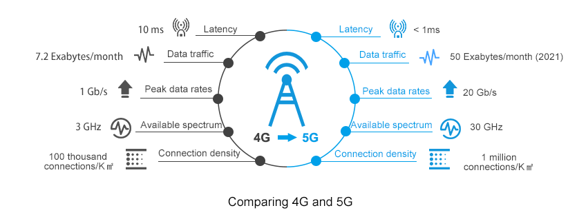
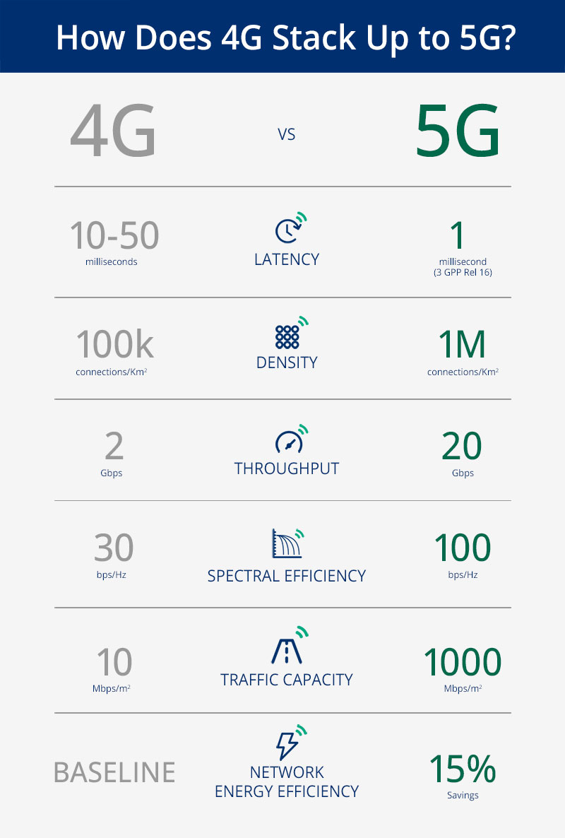
4G Vs. 5G Key Technology Differences
Choosing the right cellular technology isn’t always straightforward, but that’s where we can help. Whether you’re evaluating LPWA, LTE, or NR, we’d be happy to discuss your application, and help you navigate the intricacies of module selection to find the best fit for your project.
In this article, I will address and review the Key technology differences between 4G and 5G; reading this topic is crucial, especially if you have a good background in 4G and have just started your 5G Career.
This article will cover the differences between 4G & 5G for the following
Content
RAN Structure: 4G, 5G NSA & 5G SA
From the Radio Access Network side, The overall structure looks very similar, for example;
X2 interface connecting different 4G Nodes was replaced by the Xn interface
S1 interface connecting BTS Side to the Core network replaced by Ng interface
MME replaced by AMF and SGW replaced by UPF
From a superficial view, it is a matter of naming change; however, there are subtle changes implemented that leads to huge improvement; we will be addressing one of the points which can lead to improving latency in 5G SA.
RAN Structure
One of the main differences provided in 5G SA Architecture is that the User plane and Control function has separated; see below comments and the 4G & 5G Full Architecture for more details.
An important Characteristic of the 5G System is separating the user plane and control plane functions, which differs from the original 4G System architecture in the following:
In 4G: P-GW provides both control plane and user plane functions(IP Address allocation & Packet Forwarding)
In 5G: SMF Provides IP Allocation, and UPF provides packet forwarding
2. User and Control plane separation allows independent scaling of the two functions
Operators can add more user plane capabilities without having to add more control plane
Minimize latency by distributing User plane and keeping it geographically close to the AN
Packet Gateway provides both User plane and Control Plane function in 4G
4G Architecture
While in 5G, Only UPF provides User plane function.
5G Architecture: Pictures captured from 5G NR in Bullets
Quality of Service: 4G & 5G
For the QoS Part, there is an essential change in the way of how the QoS is being allocated.
In 4G, EPS Bearer is responsible for providing E2E User Plane connectivity between the UE and Access Point Name “APN” within the Packet Gateway
*APN defines the interface to the external data network
The point here is that EPS Bearer has a one-to-one mapping to the QoS, This means that the User needs to establish a new EPS bearer every time there is a new QCI assignment, Only One QoS(Example QCI 9 can be assigned to one DRB) with no flexibility.
4G QoS
In 5G, PDU Sessions is responsible for providing E2E User Plane connectivity between the UE and Data Network Name “DNN” within the User Plane Function ( UPF)
*DNN defines the interface to the external data network
However, Unlike 4G EPS Bearer, PDU Session supports one or more QoS Flows, Which means that QoS Flow to radio bearer mapping is not necessarily one-to-one mapping and multiple QoS can be mapped to the same Radio Bearer.
5G QoS
Note: QoS Flows belonging to different PDU Sessions are mapped onto different DRBs.
Radio Protocol Stack: 4G & 5G
SDAP Primary Task:
Service Data Application Protocol (SDAP) is responsible for mapping QoS bearers to radio bearers according to their quality-of-service requirements. This protocol layer is not present in LTE but introduced in NR when connecting to the 5G core network due to the new quality-of-service handling
The new SDAP (Service Data Adaptation Protocol) primary function maps each QoS Flow onto a specific Data Radio Bearer
•Multiple QoS Flows can be mapped onto a single DRB or,
•Single QoS Flow can be mapped onto a single DRB.
Radio Protocol Stack: SDAP Layer added in User-PlaneSDAP Layer
Overall Technology Comparison
4G Vs. 5G Bandwidth
4G Supports a maximum up to 20Mhz BW, While 5G is up to 400Mhz
5G offers less Guard Band(2~5) and Higher Spectrum Utilization(Utilizing up to 95% of the Channel BW, While 4G Utilize 90%)
Up to 20x Higher Bandwidth and New Spectrum Definition. (ex. mmwave)
NR Offers Less Guard-band and Higher spectrum utilization
*Source: 3GPP TS 38.101 & TS38.104
Frame Structure Comparison: 4G & 5G
The following summarized the main differences between 4G & 5G Frame Structure
Frame and Subframe duration remained the Same for 5G
Number of Symbols in a slot is now fixed to 14 in 5G (4G is fixed to 7)
5G has a flexible numerology, which allows different configurations as the Slot Duration relies on SCS(Sduration = 1 /SCS)
5G is now using a Slot as a scheduling Unit instead of Sub-frame compared to 4G
NR RB Resource Grid is double 4G(14 vs. 7 OFDM symbols in one RB )
Physical Channel & Signals Comparison : 4G & 5G
The below table summarizes the main differences in Physical Channel and Signals
Downlink Comparison: Physical Downlink Control Channel(PDCCH)
In LTE, PDCCH control channels are always distributed across the entire system bandwidth.
NR PDCCHs are designed to transmit in a configurable control resource set (Called CORESET).
Uplink Comparison: Physical Uplink Control Channel(PUCCH)
In 4G, PUCCH is transmitted in one or more Physical Resource Blocks (PRB) at the edges of the system bandwidth and is only supporting Long-Format(duration 1 ms)
While 5G supports both Long and short format, Where short format provides the following:
1~2 Symbols over the complete
Provides Better Latency
PBCH & Synchronization Signals: 4G & 5G
There are 2 main changes in PBCH and SS compared to 4G:
PBCH and SS are now being combined into SSB
SSB Frequency domain location is flexible and can be configured at different locations based on the network requirements(4G PBCH & SS are fixed at the center of Channel BW)
Broadcast Channel Comparison: 4G & 5G
4G Provide Wide Beam coverage, while 5G provides narrow beam coverage for broadcast channels, which can improve the Coverage and Quality
Reference Signal Overhead comparison: 4G & 5G
5G Overhead is almost half 4G, and the mean reason behind that 5G has no Cell Specific Reference Signal as 4G
As you know that CRS was all the time transmitted “Always on” over the entire BW and consume a large number of resource elements within the Resource block
While 5G uses DMRS for channel demodulation instead of CRS.
PDSCH DMRS offers much less overhead compared to CRS due to the following:
DMRS is transmitted within the set of RBs allocated to PDSCH. i.e, if a UE is allocated 10RBs for PDSCH, then both PDSCH and DMRS will be transmitted across those BW
DMRS Configuration type 1 uses 6 RS within one or two symbols, which add around 3.6% up to 7% overhead to 5G, while 4G offers from 9% to 17% overhead. Please see the below picture for more details and refer to the below-attached video for more information.
Key differences in Link Budgets: 4G & 5G
4G & 5G almost have the same Link Budget Basic Methodology
Link Budget is counting all of the gains and losses from the TX through the medium(Free Space, Cables, etc.) to the receiver
Among the best-selling 5G NR modules on the market, the Quectel RM520N-GL is engineered to deliver blazing-fast connectivity for next-generation broadband applications. Supporting both 5G NR (SA/NSA) and fallback to high-speed LTE and 3G, this module ensures reliable coverage and seamless global deployment. With downlink speeds up to 4.7 Gbps and uplink speeds up to 1.25 Gbps, the RM520N-GL is ideal for applications requiring ultra-low latency and high throughput, such as industrial automation, CPE routers, telematics, video surveillance, and AR/VR platforms.
We also offer many suitable accessory for this modem.
Your device will connect to 5G. But will it be Standalone or Non-Standalone? The answer depends on the network, and the Quectel RM520N-GL handles both. With fallback to LTE and 3G, it keeps devices connected wherever they are deployed.
That flexibility is one reason it’s among the best-selling 5G NR modules available. Add up to 4.7 Gbps downlink and 1.25 Gbps uplink, and it’s a proven choice for CPE routers, industrial automation, telematics and video surveillance.
For years, the promise of 5G has been a tale of two extremes. On one end, high-speed smartphones and fixed wireless access demanding gigabit speeds. On the other, massive IoT sensors requiring years of battery life but minimal data. In the vast, fertile middle ground, a crucial category of devices has been left waiting for a cost-effective, power-efficient, yet capable wireless solution.
That wait is over. The arrival of 5G Reduced Capability (RedCap) is not just an incremental update; it’s the key that unlocks the full, diverse potential of the 5G ecosystem.
Bridging the 5G Divide: What is RedCap?
Think of the 5G spectrum as a highway system. You have the Formula 1 lanes for eMBB (enhanced Mobile Broadband) and the specialized, low-power bike paths for mMTC (massive Machine-Type Communications). RedCap effectively creates a new, smart “commuter lane”—perfectly balanced for devices that need more than a trickle of data but don’t require the expense and power drain of a full 5G modem.
Formally defined in the 3GPP Release 17 standard, 5G RedCap (also known as NR-Light) is a optimized version of 5G. It’s designed specifically for devices that fall between the high-performance and low-power extremes. By strategically reducing complexity, antenna count, and supported features, RedCap achieves a critical goal: it brings the inherent benefits of 5G—security, low latency, and mobility—to a much wider array of applications at a fraction of the cost and power consumption.
The Engineering Trade-Off: How RedCap “Slims Down”
RedCap isn’t a watered-down version of 5G; it’s a purpose-built one. It achieves its efficiency through several intelligent design choices:
Reduced Bandwidth: While high-end 5G can use up to 100 MHz in sub-7 GHz spectra, RedCap operates on a leaner 20 MHz. For most industrial sensors, health monitors, and wearables, this is more than sufficient and drastically cuts complexity.
Fewer Antennas: A flagship smartphone might have 4 receive antennas (4Rx). RedCap devices can operate with just 1 or 2 (1Rx or 2Rx). This simplification is a major driver behind reducing device size, cost, and power needs.
Half-Duplex FDD: This allows the device to either transmit or receive at a time, but not both simultaneously. By eliminating the need for a duplexer (a component that prevents interference), RedCap devices become significantly cheaper and more power-efficient. For many applications that send bursts of data, this slight trade-off is unnoticeable.
Lower Order Modulation: RedCap primarily uses 64 QAM instead of the 256 QAM found in high-end 5G. This is a more than capable modulation scheme that reduces power demands on the device’s power amplifier.
The Real-World Impact: RedCap’s Killer Applications
The theoretical benefits are clear, but where will we actually see RedCap make a difference? The answer is in three key verticals that have been hamstrung by the limitations of existing technologies.
Industrial IoT 2.0: The factory floor is a perfect environment for RedCap. Think of wireless video surveillance cameras for safety and quality control, condition monitoring sensors on high-value machinery, and programmable logic controllers (PLCs). These devices need more bandwidth than a simple LPWAN sensor but can’t justify the cost of a full 5G module. RedCap fits perfectly, offering the reliable, low-latency connection needed for modern automation.
The Next Generation of Wearables: While smartwatches today use a mix of 4G and proprietary technologies, RedCap paves the way for a new class of advanced wearables. Imagine high-performance augmented reality (AR) glasses for enterprise or rich video-streaming capabilities in a fitness band. RedCap provides the data throughput for these experiences while ensuring the device doesn’t overheat and has a usable battery life.
A New Era for Video Surveillance: City-wide and industrial security systems require high-quality, real-time video streaming. RedCap modems are powerful enough to handle 1080p or even 4K video, and their native support for network slicing means a city can guarantee a secure, uninterrupted video feed for public safety, separate from consumer traffic on the same network.
The Road Ahead: Integration and Coexistence
The rollout of RedCap is a masterclass in seamless network integration. A key feature is its “fallback” capability. RedCap devices can connect to both modern 5G Standalone (SA) networks and older 4G LTE networks, ensuring broad coverage from day one. For network operators, enabling RedCap is often a simple software upgrade to existing 5G SA cellsites, making deployment swift and cost-effective.
Looking forward, RedCap doesn’t replace existing technologies like LTE-M or NB-IoT; it complements them. It fills a crucial performance and cost gap, creating a more complete and versatile connectivity portfolio. As we move toward 3GPP Releases 18 and beyond, we can expect further enhancements in power saving and integration, solidifying RedCap’s role as the backbone for the mid-tier IoT revolution.
In summary, 5G RedCap is the missing piece in the connectivity puzzle. By making a few smart engineering trade-offs, it brings the robust power of 5G to the devices that will define the next decade of innovation—from smarter factories to advanced wearables. The 5G revolution is no longer just about speed; it’s about intelligent, scalable, and efficient connectivity for everything. And with RedCap, that future is finally within reach.
As 5G is moving in to it’s fifth generation chipset with the Qualcomm SDX8x series 3GPP Rel-18 compliant architecture, a question of the network side of 5G still lingers among many of our customers. We have already covered what 5G RedCap (NR-Light) is, it’s pros and cons and what it will mean for the future of IoT connectivity, but for the attentive reader one thing stands out: it requires 5G SA. And in reality, a lot of the promises of a future with 5G evolves around this technology, namely a complete 5G network, from the core (datacenter) to the RAN (base station) and everything in between being 5G.
In this post we will dive in to some of the so called options in 5G networking, the multitude of abbreviations, as well as the differences in technology.
5G Networking – Non-Standalone vs Standalone 5G New Radio
LTE Networking
Let’s start by taking a step back and look at LTE (4G) networking. The so-called Option 1 consists of an Evolved Packet Core (EPC – the 4G core network) and eNodeB (eNB – 4G cellular base stations). It can be defined as an SA option as it utilizes 4G from backend to frontend, and as long as you have a 4G LTE capable device you can connect to the network and use it’s functions as we’ve all come to know it.
Simplified picure of LTE Networking
5G networking
Non-Standalone
When looking at 5G networking, things quickly became more complex. As previously mentioned 5G NSA was introduced as a way to ease the burden on the operators when deploying 5G base stations, by utilizing part of the existing 4G network already in place. The most popular approach to this dual-networking is called Option 3 with it’s abbreviation EN-DC (E-UTRA-New Radio Dual-Connectivity – IE 4G and 5G dual-mode).
Worth noting is that Option 3 in turn contains 3 sub-options 3, 3a and 3x. Most of which are available in eMBB (high-speed) 5G modules today, but notably not in RedCap.
By using NSA the modules and network uses some intelligence to know when to utilize the 5G side of the network, vs the 4G side of the same. This has been around for quite a while now, and we are starting to see 5G SA investments increasing globally.
Simplified picture of 3x, as we can see here, the 4G core of the network is connected with both an LTE eNB and 5G gNB (base station).
Simplified picture of NSA
Standalone
5G SA is the final step in the migration to 5G networks, where you switch the core of the network itself to 5G so that it acts as option 1 but with 5G, now called option 2. Don’t get us wrong, it’s nowhere near as easy as “remove this and replace with that” but in an overly simplified manner it now looks like the picture below.
Simplified picure of 5G SA
The options a module can work with are typically outlined in the datasheet or hardware guide. As mentioned above however, most new eMBB (high-speed) 5G modules can use both 5G NSA (typically ENDC Option 3/3a/3x) and 5G SA (Option 2) + LTE fallback (Option 1).
If you want to learn more about Standalone deployments, Ookla and Omdia has released a report with information on the current state of deployments: https://www.ookla.com/articles/europe-5gsa-2025
And the winner is …. SIMCom SIM8262E 5G modem! Please read bellow and compare
LTE modem SIMCom SIM8262E (5G modem)
cooling : none
connection : USB A -> mPCIe converter + mPCIe -> m.2 adapter (USB 3.0)
Consumption :
o idle (4G): 0.3-0.5, at ping (5G) jumps up to 1.3 W o flood ping (5G): 1.2-1.9 W (mostly ~1.6 W) o speedtest (5G): varies widely 2.1W-4.5 W, speeds vary from about 10 Mbps
Temperature :
o idle: ~39 ˚C o flood ping: ~62 ˚C o speedtest: ~83 ˚C
LTE modem Telit LM940
cooling : none
connection : modem plugged in USB to mPCIe converter
transmissions: alternately approx. 90 Mbps download and 30 Mbps upload
Consumption : – when actively transmitting 2.2-3 W – aggregation 2100 MHz/20 Mhz + 1800 MHz/20 MHz and 800 MHz/10 MHz – when uploading about 0,5 W higher – during simultaneous upload and download consumption at the level of separate download – during flood pinging the modem runs only on 2100 MHz, the remaining aggregated bands are inactive – consumption ~1 W – when inactive consumption fluctuates between 0.3 W and 1 W – AT commands – once every 30 s check ping
Temperature : – settled to 38 ˚C when inactive – climbed to 73 ˚C when active
LTE modem Telit LM920
cooling : none
connection : USB A -> mPCIe converter + mPCIe -> m.2 adapter (USB 3.0)
transmissions: alternately approx. 70 Mbps download and 30 Mbps upload
Consumption :
+ at rest (no explicit load, only MMngr) varies between 0.25 W and 1 W ▪ at worse signal (without antennas) higher on average by about 0.3 W, (0.25-1,3 W) + flood ping ~0.75 W (2100 MHz/20 MHz) (very stable, repeatedly measured) ▪ flood ping + speedtest as flood ping alone + speedtest in loop: fluctuates between 1.5 W and 2.5 W ▪ when uploading ~0.5 W higher (1.5-2 W/2-2.5 W) ▪ band aggregation • 2100/20 MHz • 1800/20 MHz • 800/10 MHz
connection : modem plugged in USB to mPCIe converter
transmissions: 5G avg. 130/50 Mbps
LTE avg 145/60 Mbps
after some time it disconnects from the mains (thermal fuse?)
Consumption :
o FW: FDE.F0.0.0.1.3.DT.004.046 o connection: reducer USB-A -> mPCIe + mPCIe -> m.2 o consumption (increases noticeably with modem temperature): o AT+CFUN=0: <0,5 W o idle connected: 0,5 W o 5G ▪ flood ping: 2–2,2 W ▪ speedtest: 3–3,5 W/3,5–4,5 W (Down/Up) o LTE mode – flood ping: 1,3–1,5 W – speedtest: 2,2–3 W / 3–6 W (Down/Up)
Temperature :
o AT+CFUN=0: 38 ˚C o idle connected: 38 ˚C o flood ping (5G): 70 ˚C o flood ping (4G): 56 ˚C o speedtest (5G): 85+ ˚C (connection lost) o speedtest (4G): 85+ ˚C (connection lost)
In the rapidly evolving landscape of communication technology, the advent of 5G has emerged as a groundbreaking force, promising to redefine the way we connect and communicate. As the fifth generation of wireless technology, 5G brings unprecedented speed, reliability, and low latency, setting the stage for transformative changes across various industries.
>Lightning-Fast Speeds: Redefining Connectivity
One of the most significant advancements that 5G brings to the table is its remarkable speed. With data transfer rates up to 100 times faster than its predecessor, 4G, 5G opens the door to near-instantaneous downloads, seamless streaming, and real-time communication. This speed revolutionizes the user experience, enabling applications that were once impractical, such as augmented reality (AR) and virtual reality (VR), to flourish.
>Low Latency: Enhancing Real-Time Interactions
Low latency, or the minimal delay in data transmission, is a critical aspect of 5G technology. This reduction in lag is particularly crucial for applications that demand real-time interactions, such as online gaming, video conferencing, and autonomous vehicles. The responsiveness of 5G ensures that actions and communications occur almost instantaneously, creating a more immersive and efficient user experience.
>Internet of Things (IoT): Connecting the Unconnected
5G is a catalyst for the widespread adoption of the Internet of Things (IoT). The enhanced connectivity and capacity of 5G networks can support a massive number of devices simultaneously, paving the way for a seamlessly interconnected world. From smart homes and cities to industrial automation, 5G empowers the growth of IoT applications, fostering greater efficiency and convenience in our daily lives.
>Transforming Industries: From Healthcare to Manufacturing
The impact of 5G extends beyond personal communication to reshape entire industries. In healthcare, for instance, 5G enables remote patient monitoring, telemedicine, and faster transmission of medical data, revolutionizing healthcare delivery. In manufacturing, the low latency of 5G facilitates the implementation of smart factories, where machines can communicate and coordinate in real time, optimizing production processes.
>Challenges and Considerations
While the promise of 5G is immense, it comes with challenges. The deployment of 5G infrastructure requires substantial investment, and concerns about security and potential health effects have sparked debates. Striking a balance between reaping the benefits of 5G and addressing these challenges is crucial for the successful integration of this technology.
>Global Connectivity and Collaboration
5G technology also holds the potential to bridge digital divides globally, providing reliable connectivity in remote areas and fostering collaboration on a global scale. As nations continue to roll out 5G networks, international cooperation becomes essential to create a cohesive and interconnected digital ecosystem.
In conclusion, 5G technology is ushering in a new era of communication, characterized by unparalleled speed, low latency, and transformative possibilities. As the world becomes more interconnected, the societal, economic, and technological impacts of 5G are set to reshape the way we communicate and collaborate, unlocking a future of innovation and connectivity.
We are using the prerelease firmware with AB21 now. Very stable, can support DUAL SIM (Dual LTE module) applications well. Unfortunately can not support WiFi6 modules. This is the next goal for developers. Also the current QFirehose that rooter use is too old, so if you need upgrade firmware of your Quectel module, then we recomend to use X-WRT firmware and install the plug in to upgrade the firmware – QFirehose.
This firmware can support latest Quectel and SIMCOM 5G modems like RM510x, RM520x, RM530x, SIM8262E-M2 and more
We like the X-WRT firmware performance. X-wrt fully support wifi6 ( Mediatek MT 7915 / 7916 chipset supported), has full HW-NAT support WWAN and wifi6. Support dual-lte or 5G modem load-balance , see instructions bellow. This new fw also has introduce new Quectel QMAP protocol , it will reduce the cpu load! You can use this protocol for all 5G Quectel modems.
Attention – X-wrt default IP address is http://192.168.15.1/ username admin password admin. Default X-WRT information: SSID:X-WRT_XXXX. SSID Password:88888888.
It also supports the new RM520N-GL. But it not have auto configuration for LTE modems (Rooter firmware has it only). You need manual create new interface (QMAP cellular) and manual choose AT port to display modem signal information. Please see it in instructions bellow.
And how to set up the load balance for for two LTE modems and two SIM cards at H721 router?
First you need install 2 modems at M.2 and Mini-picie slot and sim cards, this example use RM502Q-AE and EP06 modems
Normally Mini-pcie modem will power up first and M.2 modem will power up secondly . So system will create Modem subsystem In sequence. That is to say, CDC-wdm0 & ttyUSB0 ttyUSB1 ttyUSB2 is Mini-pcie modem, CDC-wdm1 & ttyUSB3 ttyUSB4 ttyUSB5 is M.2 modem.
Delete all usbwan* at Network-interface
save & apply
Open network-Xwan, check enable xwan, set 3 at Number of xwan, check Auto balanced setup , set ip 8.8.8.8 at Tracking hostname or IP address IPv4 and IPv6 at Internet Protocol
save &apply
Wait for 30 second, network-interface change xwan01 general settings Protocol QMAP Cellular switch protocol Modem device /dev/cdc-wdm1 (M.2 modem) input your apn and related info. Advance settings. Set Use gateway metric 801 . Firewall settings.
Setup xwan02. pay attention, modem device /dev/cdc-wdm0(Mini-pcie modem) and metric use 802
Save and apply admin
After you finish settings, you can check the Mwan status at status-MultiWAN Manager
You can also set more at network-MultiWan Manager, such as Wan priority at Member Metric
.
.
Czech language instructions :
1. síť, rozhraní, odstranit všechna rozhraní usbwan** uložit a použít nastavení
2. síť, multi-dial, zapnout multi-dial, 3-dial sledování hostitele zachovat bránu, ostatní odstranit, protokol vybrat ipv4 a ipv6 uložit a použít nastavení
An APN (Access Point Name) is the gateway configuration that tells your cellular module which network path to use when connecting to the internet or a private data network. Think of it as the “address” your device hands to the carrier to establish a data session. It determines routing, IP assignment, and in many cases, what security policies apply to your traffic.
APNs exist because carriers need to route data traffic to different destinations: a consumer browsing social media, a fleet vehicle reporting GPS, and a medical device uploading readings all have very different requirements – and the APN is how the network tells them apart.
In IoT deployments, leaving the APN on auto-detect is a common mistake. Manually setting it ensures your device consistently connects to the right context, especially critical when using IoT SIMs, private APNs with fixed IPs, or roaming SIMs where auto-selection can land you on a suboptimal or even incorrect bearer. A wrong or missing APN means no data, silent failures, and hours of debugging that could have been avoided with a single AT command.
How to set “my APN” in a cellular module?
By default, cellular modules come without a pre-defined APN (Access Point Name). It is however best practice to set this to the correct value to tell the module how to get online
AT+CGDCONT=1,"IPV4V6","techship.com" // Set APN
OK
AT+CGDCONT? // Query APN
+CGDCONT: 1,"IPV4V6","techship.com","0.0.0.0.0.0.0.0.0.0.0.0.0.0.0.0",0,0,0,0,,,,,,,,,,"",,,,0
AT+CFUN=1,1 // Restart the module for settings to take effect
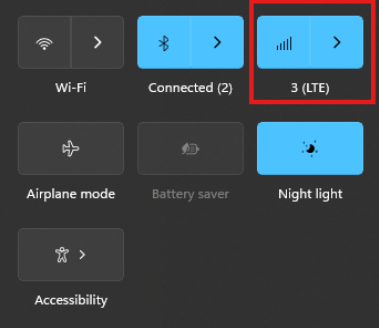
Via Windows GUI:
The connection manager settings and controls can be found and accessed on Windows desktop start menu through the network icon (see picture)
The Cellular tab can be found in Windows system settings and the connection APN details can be manually entered through “Advanced options”
Via Linux ModemManager/NetworkManager:
Using NetworkManager and ModemManager in Linux to automatically establish a connection and configure IP details
In this article we will show how to set up NetworkManager to automatically configure, establish the cellular data connection in your system.
NetworkManager and ModemManager are open source tool for Linux to manage several types of networks and interfaces such as ethernet, wifi, etc. It can also manage cellular WWAN interfaces through the ModemManager tool. It is hosted by the Freedesktop.org community and driven by Aleksander Morgado and other contributors. please visit https://wiki.gnome.org/Projects/NetworkManager and https://www.freedesktop.org/wiki/Software/ModemManager/ for latest information, source code, API reference manuals, debugging tips, contribution, mailing list etc.
ModemManager is capable of communicating over several types of device control channels such as QMI/RMNET, MBIM, MODEM / AT command etc. But support for vendor proprietary or out-of-kernel drivers are none or very limited. Such drivers are gobinet, simcom_wwan and other drivers provided by the vendors directly.
Many Linux distributions have NetworkManager and ModemManager pre-installed or they can typically easily be installed through the systems package manager. In Ubuntu for example apt can install it for you by command if not already installed: apt install network-manager
Check with commands below that you have both tools installed in system and their versions. NetworkManager -V ModemManager -V
ModemManager (and NetworkManager) are continuously developed for better compatibility with the cellular devices, therefore it is recommend to use a recent version of the tools and in case of problem situations, evaluate the latest versions from source and check the mailing list archives for possible discussions on the problem experienced.
Keep in mind that NetworkManager and ModemManager projects are not directly developed or driven by the cellular device vendors and the compatibility with the device you aim to use can be limited. Some vendors contribute with code to make their devices fully compatible, while others don’t. Many cellular devices can be set to expose standardized types of USB network interface and control channel such as MBIM interface by USB-IF or the Qualcomm proprietary interface QMI that ModemManager will try to identify, and often manage to work successfully with but there are exceptions also.
Both NetworkManager and ModemManager have command line interfaces (nmcli and mmcli respectively) where you can interact with the management tools.
Have ModemManager list all the cellular device it has detected. Here we use the Alcatel IK41 series with MBIM interface in this example: mmcli –list-modems /org/freedesktop/ModemManager1/Modem/0 [Alcatel] Mobilebroadband
Check that the cellular device is managed by NetworkManager by not having state “unmanaged” listed for it. nmcli device status DEVICE TYPE STATE CONNECTION cdc-wdm0 gsm disconnected — enp3s0 ethernet unmanaged — lo loopback unmanaged —
Now you should create a connection profile in NetworkManager for your specific network carrier and SIM card with the “nmcli connection add” command: For example: nmcli connection add type gsm ifname ‘*’ con-name ‘3-sweden’ apn ‘data.tre.se’ connection.autoconnect yes gsm.pin 0000
– type is gsm for all typical cellular connections unless it is of cdma type. – ifname is the control interface name, in this case cdc-wdm0, wildcard can be used also to have it autoselect. – con-name is the profile name you want to give it. – apn is provided by your network carrier and tells the modem what attach point it should use for the data connection. – connection.autoconnect set to yes will make NetworkManager always try to auto connect and maintain this profile connection. – gsm.pin lets you provide a pin code for the SIM card, that NetworkManager will try to use if PIN check is enabled for SIM card.
There are several additional commands and attributes available such as username and password settings for the APNs etc. Refer to the NetworkManager help and manual pages for full details on the commands.
If successful you should receive a reply similar to this one: Connection ‘3-sweden’ (cad6fcbf-2cb1-4796-b7e6-67b9f9635aef) successfully added.
You can check the status now by command: nmcli device status DEVICE TYPE STATE CONNECTION cdc-wdm0 gsm connected 3-sweden enp3s0 ethernet unmanaged — lo loopback unmanaged —
Where connected should be listed as state if the connection establishment was successful.
If the connection is not successful or you want more details about the device and connection you can check commands:
You can list the current status with command: nmcli radio WIFI-HW WIFI WWAN-HW WWAN enabled enabled enabled enabled
nmcli connection show NAME UUID TYPE DEVICE 3-sweden e946017f-2e9c-477b-89ad-4c31e7331d65 gsm cdc-wdm0
Ifconfig should now show the related IP address details already set to the network interface by NetworkManager: ifconfig wwan0: flags=4291 mtu 1500 inet 2.68.73.130 netmask 255.255.255.252 broadcast 2.68.73.131 inet6 2a02:aa1:1017:6d11:6474:7254:7b72:eb09 prefixlen 64 scopeid 0x0 inet6 2a02:aa1:1017:6d11:1060:3dff:feac:e92f prefixlen 64 scopeid 0x0 ether 12:60:3d:ac:e9:2f txqueuelen 1000 (Ethernet) RX packets 186 bytes 10886 (10.8 KB) RX errors 0 dropped 0 overruns 0 frame 0 TX packets 5 bytes 480 (480.0 B) TX errors 0 dropped 0 overruns 0 carrier 0 collisions 0
You can now for example test the connection over the network interface by sending ping requests. Testing IPV4 connection: ping -4 -I wwan0 8.8.8.8 PING 8.8.8.8 (8.8.8.8) from 2.68.73.130 wwan0: 56(84) bytes of data. 64 bytes from 8.8.8.8: icmp_seq=1 ttl=118 time=55.8 ms 64 bytes from 8.8.8.8: icmp_seq=2 ttl=118 time=45.4 ms 64 bytes from 8.8.8.8: icmp_seq=3 ttl=118 time=42.9 ms — 8.8.8.8 ping statistics — 3 packets transmitted, 3 received, 0% packet loss, time 2003ms rtt min/avg/max/mdev = 42.918/48.053/55.845/5.601 ms
Testing IPV6 connection: (if your cellular device, network subscription and APN supports it) ping -6 -I wwan0 2600:: PING 2600::(2600::) from 2a02:aa1:1017:6d11:1060:3dff:feac:e92f wwan0: 56 data bytes 64 bytes from 2600::: icmp_seq=1 ttl=46 time=172 ms 64 bytes from 2600::: icmp_seq=2 ttl=46 time=171 ms 64 bytes from 2600::: icmp_seq=3 ttl=46 time=169 ms 64 bytes from 2600::: icmp_seq=4 ttl=46 time=168 ms — 2600:: ping statistics — 4 packets transmitted, 4 received, 0% packet loss, time 3004ms rtt min/avg/max/mdev = 167.921/170.037/172.272/1.651 ms
The connection is successful and automatic reconnect is working when testing to unplug and plug in the device again. For additional configurations, commands and available attributes, please relate to the manual pages for NetworkManager and ModemManager.
Troubleshooting logs: NetworkManager and ModemManager write log messages to the Linux syslog file /var/log/syslog. In case of problems with establishing a cellular data connection, please copy the logfile after the problem have appeared and include it in a Techship technical support ticket.
In some situations more detailed debug logs are needed, these can be acquired by changing the log levels for NetworkManager and ModemManager and run them manually.
To capture debug logs, please first disable and stop the normal services: systemctl stop NetworkManager ModemManager systemctl disable NetworkManager ModemManager
Run them manually in background with debug level set: /usr/sbin/ModemManager –log-level=DEBUG &> /dev/null & /usr/sbin/NetworkManager –log-level=DEBUG &
Reproduce the cellular data connection problem. Once completed, kill the processes: killall -TERM NetworkManager ModemManager
Copy the relate messages in syslog to a mm-nm-sys-debug.log logfile: grep -E ‘ModemManager|NetworkManager|systemd|dbus-daemon|dhclient’ /var/log/syslog > mm-nm-sys-debug.log
Activate and start the services again: systemctl enable NetworkManager ModemManager systemctl start NetworkManager ModemManager
Include the mm-nm-sys-debug.log in a technical support ticket at Techship.com where you describe the issue in details and include other relevant information also such as kernel version, ModemManager and NetworkManager versions, dmesg log etc.
Empowering Customization and Connectivity: The IPQ4019-Based Industrial Board
In the realm of industrial connectivity, adaptability reigns supreme. Introducing the IPQ4019-based industrial board, a versatile solution engineered to offer unparalleled customization and connectivity options. Let’s explore its key features:
Tailored Dual LTE Support
– This board supports customizable configurations for dual LTE support, allowing for routerboard/baseboard+SOM setups tailored to specific requirements. Whether it’s optimizing bandwidth or ensuring redundancy, users can fine-tune their connectivity solutions with ease.
Efficient Network Segmentation via VLANs
– Recognizing the importance of network segmentation, this board seamlessly integrates VLAN support. Users can create distinct virtual networks within a single physical infrastructure, enhancing security and efficiency.
Customized LUCI Interface
– Elevate brand identity and user experience with a customized LUCI interface featuring the customer’s logo. This personalized touch adds a professional flair while maintaining familiarity for end-users.
Extended Range Firmware Customization
– Break through geographical barriers with custom firmware designed for long-distance transmission, reaching up to 20km. Whether it’s remote installations or expansive deployments, rest assured that firmware updates will reach even the most remote endpoints.
Seamless Integration with Leading Controllers
– Integrate effortlessly into existing network architectures with support for Wallys AP Controller and TIP Cloud Controller. Benefit from centralized management, configuration, and monitoring capabilities, enhancing operational efficiency and scalability.
Conclusion: Unmatched Flexibility for Industrial Connectivity
In conclusion, the IPQ4019-based industrial board stands as a beacon of innovation and adaptability in industrial connectivity. With its support for customizable LTE configurations, VLANs, branded interfaces, long-distance firmware transmission, and integration with leading management controllers, this board offers unparalleled flexibility and connectivity options. Whether optimizing performance, enhancing security, or streamlining operations, this versatile solution is poised to revolutionize industrial connectivity challenges.
DR4019
Featuring with industrial-grade IPQ4019/IPQ4029 chipset
Integrated with 2x 2 5G high power Radio module and 2×2 2.4G high power Radio module
Support 4.940GHz to 5.825GHz Frequency Range
Support 2.400GHz to 2.482GHz
Support 2 x 5G MMCX Connectors and 2×2.4G MMCX
Support 5MHz/10MHz/20MHz/40MHz/80MHz Bandwidth
Support 11ABGN/AC
Support fixed data rate
RoHS compliance ensure a high level protection of human health and the environment from risks that can be posed by chemicals