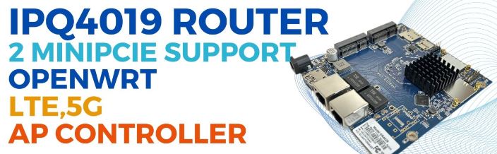
Empowering Customization and Connectivity: The IPQ4019-Based Industrial Board
In the realm of industrial connectivity, adaptability reigns supreme. Introducing the IPQ4019-based industrial board, a versatile solution engineered to offer unparalleled customization and connectivity options. Let’s explore its key features:
Tailored Dual LTE Support
– This board supports customizable configurations for dual LTE support, allowing for routerboard/baseboard+SOM setups tailored to specific requirements. Whether it’s optimizing bandwidth or ensuring redundancy, users can fine-tune their connectivity solutions with ease.
Efficient Network Segmentation via VLANs
– Recognizing the importance of network segmentation, this board seamlessly integrates VLAN support. Users can create distinct virtual networks within a single physical infrastructure, enhancing security and efficiency.
Customized LUCI Interface
– Elevate brand identity and user experience with a customized LUCI interface featuring the customer’s logo. This personalized touch adds a professional flair while maintaining familiarity for end-users.
Extended Range Firmware Customization
– Break through geographical barriers with custom firmware designed for long-distance transmission, reaching up to 20km. Whether it’s remote installations or expansive deployments, rest assured that firmware updates will reach even the most remote endpoints.
Seamless Integration with Leading Controllers
– Integrate effortlessly into existing network architectures with support for Wallys AP Controller and TIP Cloud Controller. Benefit from centralized management, configuration, and monitoring capabilities, enhancing operational efficiency and scalability.
Conclusion: Unmatched Flexibility for Industrial Connectivity
In conclusion, the IPQ4019-based industrial board stands as a beacon of innovation and adaptability in industrial connectivity. With its support for customizable LTE configurations, VLANs, branded interfaces, long-distance firmware transmission, and integration with leading management controllers, this board offers unparalleled flexibility and connectivity options. Whether optimizing performance, enhancing security, or streamlining operations, this versatile solution is poised to revolutionize industrial connectivity challenges.
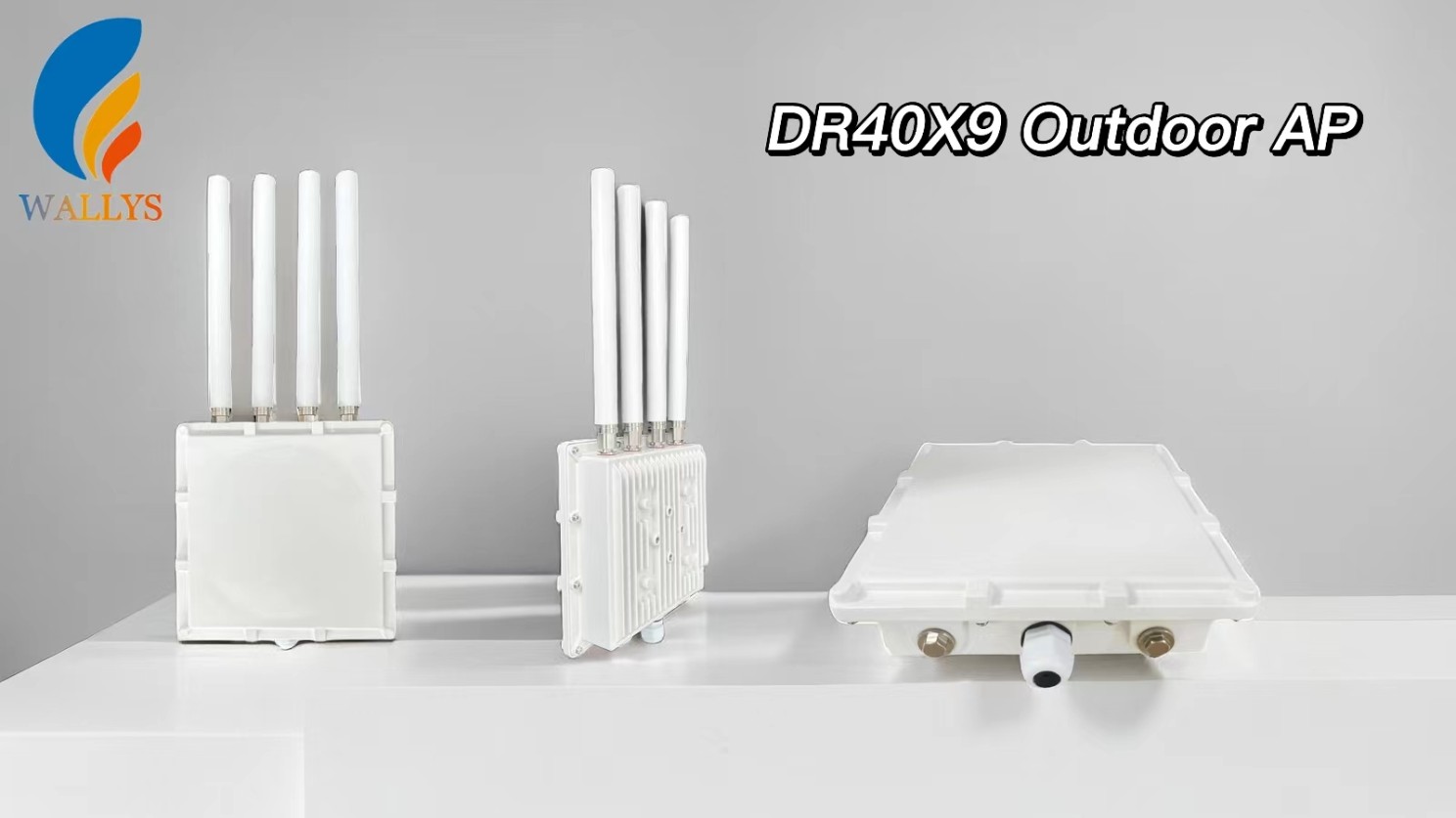
DR4019 / DR4029
Featuring with industrial-grade IPQ4019/IPQ4029 chipset
Integrated with 2x 2 5G high power Radio module and 2×2 2.4G high power Radio module
Support 4.940GHz to 5.825GHz Frequency Range
Support 2.400GHz to 2.482GHz
Support 2 x 5G MMCX Connectors and 2×2.4G MMCX
Support 5MHz/10MHz/20MHz/40MHz/80MHz Bandwidth
Support 11ABGN/AC
Support fixed data rate
RoHS compliance ensure a high level protection of human health and the environment from risks that can be posed by chemicals
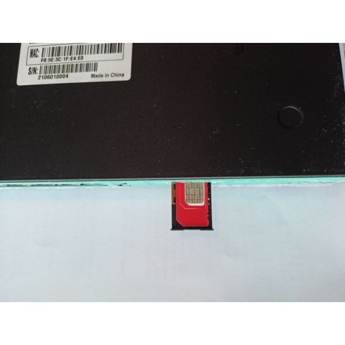
Put a functional SIM card into the SIM slot (please see picture bellow).
Please bear in mind that there are 2 types of antennas: LTE and WiFi. Be sure that you’re putting in the right antenna to the right slot, You can recognize them by female and male connectors.
After ensuring that everything is in the right place, please first connect your LANport then the routers DC interface, please use 12V / 2A power adapter.
Now type into your browsers URL query “192.168.1.1” it’ll take you to the routers firmware
Passwords are: Viper firmware “Password1234” or “admin” for OpenWRT
WiFi default password: Viper firmware “LakeWater561” , in OpenWRT firmware is WiFi without encryption by default.
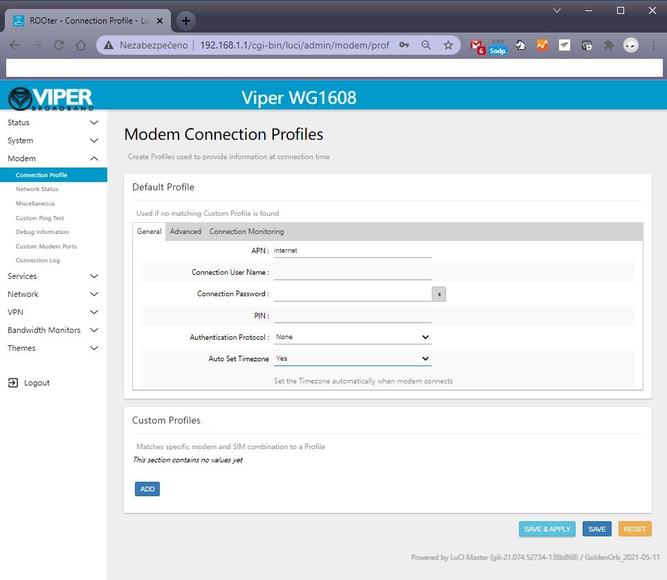
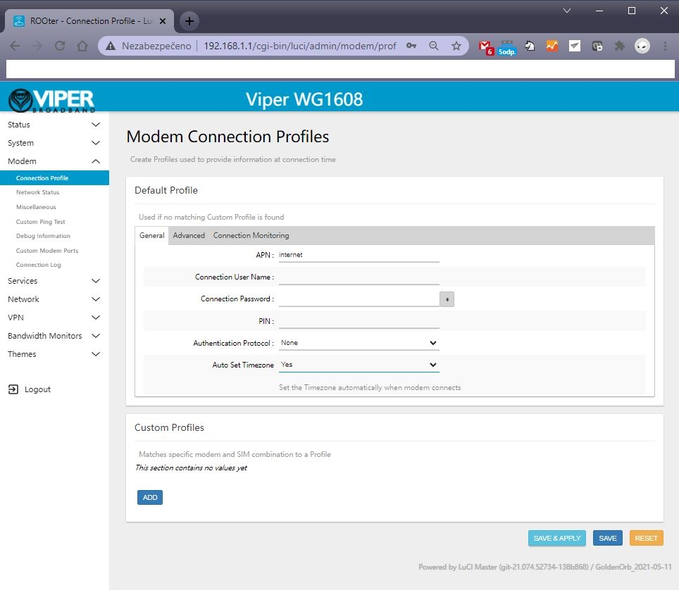
After getting inside your firmware please go to “Modem > Connection profile” and set your APN to “internet” or other APN from your provider and wait at least 5 minutes.
A few of the more common carrier APNs are listed below:
Don’t forget to check “Modem > Network Status” to see if your router recognizes:
Your SIM card
Your modem
Strength of your signal
If you see every mentioned option in No. 6 then congratulations!!! Your router is ready to be deployed. We hope that this user manual was helpful. We’re trying to keep it as simple as humanly possible.
We set customers own specific settings as long as they’re mentioned in the order note.
If you have any more questions, please be sure to contact us at [email protected].
ADVANCED SECTION
QUECTEL RM520N-GL, RM502Q AND OTHER QUECTEL MODULE SETUP IN OPENWRT FIRMARE :
1 – go to the Network – Interfaces – 4G menu and check the 4G/5G module button , then you can set the APN
2 – Then save and reboot and you can see 4G/5G connected in Status page :
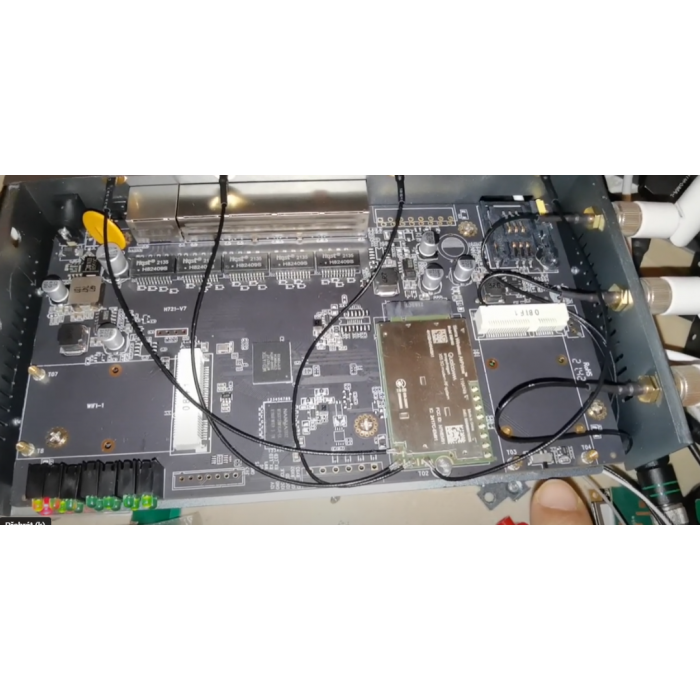
Please insert your 4G or 5G LTE card in “M.2 LTE card slot”
Connect your pigtails to your LTE card and your WiFi card (If there’s a right slot for it marked with “WiFi” text)
A) is the correct way.
B) This one isn’t as this may result in damaging contact between the LTE card and antenna.
This tutorial will demonstrate the build and configuration process for the M2M 5G LTE H721 Dual Modem Router.
2023 note : This popular router can support new popular 5G modules like Quectel RM502 Q, RM520N or Sierra Wireless 5G modems. New switch just for Sierra Wireless EM919x and EM7690, these card default work at PICE mode. We add new switch just let EM919x EM769x work at USB mode. Please see this video : https://www.youtube.com/watch?v=whKcn4SFMKQ
1 – New firmware has support AW7916 / AW7915 wifi 6 modules. Do not support QCN wifi 6.
2 – It supports RM520N-GL. X-WRT soft engineer use RM520N . You need manual create new interface (QMAP cellular) and manual choose AT port to display modem signal information
3 – New fw has introduce new Quectel QMAP , it will reduce cpu load.
4 – Full support hw-nat, 5 – Support dual-lte or 5G modem load-balance (see instruction.)
The modem signal Luci is still in development.
Please note, Wodaplug ( 524wifi.com ) are using V7 unique rebuild version of this popular modem for full 5G equiped with protection, pls note – some pictures of older versions may be not coresponding to your newer model. Good new also is that we just finish 5G_NR signal status page and Simcom 8200 5G modem support.
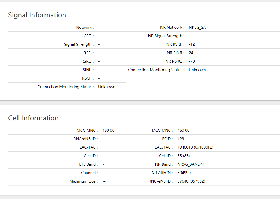
5G Signal information displayed by our router
There are many possible build variations for building the M2M. Autor decided to use a single EM7565 CAT12 M.2 modem and dual mini PCI-E WiFi cards—one for 2.4GHz and the other for 5GHz WiFi.
The WiFi cards used in this build are dual band cards, but each card may only operate on one band at a time—either 2.4GHz or 5GHz. The QCA AC WiFi card will work well for its higher speed capabilities on the 5GHz WiFi, while the Atheros WiFi card will handle the 2.4GHz WiFi. New firmware support Ath10k 802.11AC Wave2, about 20% improvement at Wifi 5.8G support QCA9984 QCA9886 QCA9888
The components used for this particular build are:
(1) Small Phillips Head Screwdriver (1) Small Standard Head Screwdriver (1) 5/16 Nut Driver, Socket or Wrench (1) Wooden Chopstick with Tip Sanded Flat (or similar object to use for connector attachments)
OPENING THE ROUTER CASE:
There are seven screws in total to remove before separating the router case. This is required to obtain access to the router PCB to install the Modem, WiFi Cards and Pigtail connectors.
Place the router on a flat table or surface with the lower case decal facing up.
Remove the three screws along the upper edge.
Remove the two screws from each side of the router.
After removing all seven screws, carefully slide the lower case back about an inch from the upper case.
Hold the lower and upper case in their position and carefully flip the router into its upright position.
Remove the Upper Case from the router assembly to expose the PCB (Printed Circuit Board).
The EM7565 is be mounted in the M.2 interface slot labeled #3
The 5 Volt WiFi Card is to be mounted in the Mini PCI-E interface slot labeled #2 since it supports both 3.3 and 5 Volt WiFi Cards.
The Atheros WiFi Card is to be mounted in the Mini PCI-E interface slot labeled #1
(Note: The M.2 interface slot #4 on the underside of the PCB for a second modem is not being used for this build).
Carefully slide each of the modem and WiFi cards into their proper interface slot—paying special attention to the proper key/pin alignments—and secure each of the cards in place with the screws that are included (shown in the red circles):
INSTALLING THE ANTENNA PIGTAIL CONNECTORS
There are 12 different antenna cutouts and plastic plugs that should accommodate most any antenna configuration. Decide what antenna placements work best for a particular build.
Below is the antenna configuration used for this build which works rather well.
Remove the plastic plugs from both upper and lower case to be used for the antennas.
Place each of the WiFi RP-SMA and Cellular (LTE) SMA antenna pigtail connectors into their proper cutout slot.
Consideration should be given as to the length of cable being used in relation to the location of the WiFi card or modem it will be connected to.
Notice that the SMA and RP-SMA antenna connectors appear similar, but they are different. One is not compatible with the other. Generally, WiFi uses RP-SMA while cellular uses SMA. The differences can be seen on the following image:
Place the star and lock washers over the connector and secure in place with the nut. Use the 5/16 nut driver to snug the connector nut—but do not over-tighten.
Now the modem and WiFi cards are installed and secured in place with their screws, and the pigtail connectors are installed in the upper and lower case, it is time to install the pigtail’s U.FL and MHF4 connectors to the cards.
Care must be exercised when working with these connectors to avoid damaging the tiny connectors or ports on the modem. Good lighting is crucial and a magnifying glass will be extremely useful.
When connecting these connectors, make certain they are flat and aligned perfectly with the connector port of the modem. A flat instrument placed on top of the connector (the wooden chopstick in this example) will help to snap the connector evenly in place.
Do not force the connects. If they do not snap/pop into place with slight downward pressure, chances are the connector and port are not aligned.
Once the connectors are installed, the Selector Switch on the PCB must be set for this particular configuration. According to the documentation, when using the M.2 slot #3 for the modem, and a WiFi Card in the Mini PCI-E slot #1, the Switch should be in the down position:
Switch selector (optional – depends on model – wodaplug.com new V5G version does NOT have switch)
Confirm the switch is in the down position (for older HW versions only):
The Upper and Lower cases may now be reassembled and secured with the seven screws.
The antennas may also be installed in their proper positioning.
CONFIGURING ROUTER WITH GOLDENORB
The M2M NEXG H721 Dual Modem Router comes with GoldenOrb firmware preinstalled which helps to simplify the overall router build and configuration.
Plug the 12 Volt power supply into the power plug on the router.
Connect an Ethernet cable from one of the LAN ports on the router to the Ethernet plug on the PC.
(Note which SIM Card slot will be used for the EM7565 but DO NOT install the SIM Card until after GoldenOrb is configured and ready to connect to the internet).
1. LAN – SIM – Power
Once the M2M router has booted up, open a web browser and enter 192.168.1.1 in the address bar and press enter. The Splash Page should appear. Click on the “Router Login”:
2. Router splash page
Log into the router using the default user name “root” (without the ““marks) and the default password of “admin”.
The default user name and password is located on the decal on the bottom of the router.
Default WiFi passwords – for older firmare version it was “12345678” , new Rooter firmware version use “rooter2017” as default WiFi password.
3. Router Login
Once logged in, the Overview screen should appear.
4. Overview screen
From the left side tabs, select System > System > General Settings.
Use the Time Zone down arrow and select the proper time zone.
Click on the Sync With Browser button.
Click Save and Apply.
(Important, any change in a GoldenOrb setting must be Saved and Applied to implement and remember the change).
5. Time zone
Go to Modem > Connection Profile > General > APN
APN stands for Access Point Name, which is required to identify and connect to a specific cellular carrier. Each carrier uses a different APN.
Type the correct APN used by your cellular carrier that is tied to the SIM Card and plan to be used in the M2M router.
Click on Save & Apply.
A few of the more common carrier APNs are listed below:
Go to System > Administration > Router Password and enter a password that will be used to log into GoldenOrb.
Some may prefer to skip this step and leave the default password of “admin”. This may be changed after all of the other configurations are made and the router is connected to the internet.
7. Setting login password
It is now time to configure the WiFi. Go to Network > Wireless.
The Wireless Overview screen will appear and show the WiFi cards installed in the router. In this build, Radio0 is the Atheros card used for the 2.4GHz WiFi network.
Click on the Radio0 Master tab at the top left of the screen.
8. Select Wireless Network Radio0
Select the Mode and Channel that the 2.4GHz network is to operate on.
In this case, N is selected for the Mode and Channel 11 is used since it has little traffic on that channel.
The Channel can be changed to another channel if the one selected becomes too congested.
There are WiFi analyzer apps that can be downloaded onto your smart phone to assist in selecting the best, non-congested channel available at your location.
Enter the ESSID that the 2.4GHz WiFi Network will be named. In this build TestHome was used.
9. Configure Atheros Radio0 2.4GHz 1
Click on the Wireless Security tab in the lower part of the Interface Configuration screen.
Select the Encryption to be used by selecting the down arrow. In this case WPA2-PSK is selected.
Under Key, enter the Password that will be used to Log onto the 2.4Ghz WiFi Network.
Click Save & Apply to save setting.
Next is to configure the 5GHz WiFi. Go to Network > Wireless and select the Radio1 Master from the top of the menu.
Radio1 is the Complex card used in this build.
11. Select Wireless Network Radio1
Select Mode and Channel that 5Ghz WiFi network is to operate on.
In this case, AC for the Mode and Channel 36 was selected since there is little traffic on this channel. This can be changed to another channel if this one becomes too congested.
Again, a WiFi Analyzer app will help make the proper selection.
Enter the ESSID that the 5GHz WiFi Network will be named. In this case TestHome5G was used.
12. Configure WiFi Radio1 5GHz 1
Click on the Wireless Security tab in the lower part of the Interface Configuration screen.
Select the Encryption to be used by selecting the down arrow. In this case WPA2-PSK is selected.
Under Key, enter the Password that will be used to Log onto the 5Ghz WiFi Network.
Click Save & Apply to save setting.
Default WiFi passwords – for older firmare version it was “12345678” , new Rooter firmware version use “rooter2017” as default WiFi password.
13. 5GHz WiFi Password and Encryption
Optional: For users who may have limits imposed by their carrier on the amount of hotspot data that may be used on a monthly basis, my want to use the TTL custom settings.
Go to Network > Firewall > Custom TTL Settings (top of the screen) > Enable > set to 65 > Save & Apply.
14. TTL Settings
Assuming all of the settings are properly configured, you should now be ready to connect to the internet. Unplug power from the router, install an activated SIM Card, plug the power back in and give it a minute or two to connect.
1 – New firmware has support AW7916 / AW7915 wifi 6 modules. Do not support QCN wifi 6.
2 – It supports RM520N-GL. X-WRT soft engineer use RM520N . You need manual create new interface (QMAP cellular) and manual choose AT port to display modem signal information
3 – New fw has introduce new Quectel QMAP , it will reduce cpu load.
4 – Full support hw-nat, 5 – Support dual-lte or 5G modem load-balance (see instruction.)
You probably know that LTE is divided in categories, shorthand “Cat” which you can see everywhere in Techship’s available documentation and website. But is higher always faster? And is a Cat-4 always a Cat-4?
The answer surprisingly is no. Let’s take an example with LTE Cat-12 which has been around for quite a while, it boasts 600Mbps DL and 150Mbps UL capabilities. So does that mean an LTE Cat-13 module is even faster? No, an LTE Cat-13 provides 400Mbps DL and 150Mbps UL. Meaning that the uplink performance is the same, but the downlink performance is different between these two categories. This generally stems from a separation of DL/UL performance in the 3GPP standards, meaning that modules from 3GPP standard before 12 conforms to a combined UE category system, and after 12 it separates the DL/UL categories. This means that what is typically defined as an LTE Cat-7 device (300Mbps DL/150Mbps UL) is actually LTE Cat-7 UE DL and LTE Cat-13 UE UL.
And our mystical comment about LTE Cat-4? Well not all Cat-4’s are the same either. LTE Cat-4 was introduced in 3GPP Release-8 with 150Mbps DL and 50Mbps UL using 64QAM. In a later release, support for 256QAM DL was introduced, meaning that newer chipsets supporting LTE Cat-4 can utilize this high downlink modulation scheme. An example being a lot of today’s 5G RedCap modules supporting LTE Cat-4 based on 3GPP Release-16.
If you want to know more about 3GPP releases, you can contact our experts, or dig through the archives at 3GPP.