The advent of 5G technology marks a significant milestone in the evolution of wireless communication, promising to revolutionize how we connect, communicate, and interact with the world around us. As we delve into the era of 5G, it’s essential to explore its potential impacts, the advancements it brings, and what lies beyond in the realm of wireless communication.
The Promise of 5G Technology
5G, the fifth generation of mobile networks, is designed to deliver unprecedented speeds, ultra-low latency, and massive connectivity. Unlike its predecessors, 5G is not just an incremental upgrade but a transformative leap forward. Key features of 5G include:
Enhanced Mobile Broadband (eMBB): Offering data speeds up to 100 times faster than 4G, 5G enables seamless streaming, rapid downloads, and high-quality video conferencing.
Ultra-Reliable Low Latency Communication (URLLC): With latency as low as 1 millisecond, 5G supports critical applications such as autonomous vehicles, remote surgery, and industrial automation.
Massive Machine-Type Communications (mMTC): Capable of connecting millions of IoT devices per square kilometer, 5G facilitates smart cities, connected homes, and industrial IoT applications.
Impact on Various Industries
The transformative capabilities of 5G extend across multiple industries, driving innovation and efficiency:
Healthcare: 5G enables telemedicine, remote monitoring, and real-time data sharing, improving patient care and access to medical services.
Automotive: Enhanced vehicle-to-everything (V2X) communication supports autonomous driving, traffic management, and vehicle safety systems.
Manufacturing: Smart factories leverage 5G for real-time monitoring, predictive maintenance, and automation, increasing productivity and reducing downtime.
Entertainment: Virtual reality (VR) and augmented reality (AR) experiences become more immersive and interactive with the high bandwidth and low latency of 5G.
Technical Advancements
The success of 5G relies on several key technological advancements:
Millimeter Wave (mmWave) Spectrum: Utilizing higher frequency bands (24-100 GHz) enables faster data transmission and greater capacity, albeit with shorter range and higher susceptibility to obstacles.
Massive MIMO (Multiple Input Multiple Output): Increases network capacity by using multiple antennas to send and receive more data simultaneously.
Network Slicing: Allows the creation of virtual networks tailored to specific applications or services, ensuring optimal performance and resource allocation.
Edge Computing: Reduces latency by processing data closer to the source, critical for applications requiring real-time responsiveness.
Challenges and Considerations
Despite its potential, 5G deployment faces several challenges:
Infrastructure Investment: Building the necessary infrastructure, including small cells and fiber optic networks, requires significant investment.
Spectrum Allocation: Efficiently managing the allocation and use of limited spectrum resources is crucial to avoid interference and maximize performance.
Security Concerns: Enhanced connectivity and increased attack surfaces necessitate robust security measures to protect against cyber threats.
In the rapidly evolving landscape of communication technology, the advent of 5G has emerged as a groundbreaking force, promising to redefine the way we connect and communicate. As the fifth generation of wireless technology, 5G brings unprecedented speed, reliability, and low latency, setting the stage for transformative changes across various industries.
>Lightning-Fast Speeds: Redefining Connectivity
One of the most significant advancements that 5G brings to the table is its remarkable speed. With data transfer rates up to 100 times faster than its predecessor, 4G, 5G opens the door to near-instantaneous downloads, seamless streaming, and real-time communication. This speed revolutionizes the user experience, enabling applications that were once impractical, such as augmented reality (AR) and virtual reality (VR), to flourish.
>Low Latency: Enhancing Real-Time Interactions
Low latency, or the minimal delay in data transmission, is a critical aspect of 5G technology. This reduction in lag is particularly crucial for applications that demand real-time interactions, such as online gaming, video conferencing, and autonomous vehicles. The responsiveness of 5G ensures that actions and communications occur almost instantaneously, creating a more immersive and efficient user experience.
>Internet of Things (IoT): Connecting the Unconnected
5G is a catalyst for the widespread adoption of the Internet of Things (IoT). The enhanced connectivity and capacity of 5G networks can support a massive number of devices simultaneously, paving the way for a seamlessly interconnected world. From smart homes and cities to industrial automation, 5G empowers the growth of IoT applications, fostering greater efficiency and convenience in our daily lives.
>Transforming Industries: From Healthcare to Manufacturing
The impact of 5G extends beyond personal communication to reshape entire industries. In healthcare, for instance, 5G enables remote patient monitoring, telemedicine, and faster transmission of medical data, revolutionizing healthcare delivery. In manufacturing, the low latency of 5G facilitates the implementation of smart factories, where machines can communicate and coordinate in real time, optimizing production processes.
>Challenges and Considerations
While the promise of 5G is immense, it comes with challenges. The deployment of 5G infrastructure requires substantial investment, and concerns about security and potential health effects have sparked debates. Striking a balance between reaping the benefits of 5G and addressing these challenges is crucial for the successful integration of this technology.
>Global Connectivity and Collaboration
5G technology also holds the potential to bridge digital divides globally, providing reliable connectivity in remote areas and fostering collaboration on a global scale. As nations continue to roll out 5G networks, international cooperation becomes essential to create a cohesive and interconnected digital ecosystem.
In conclusion, 5G technology is ushering in a new era of communication, characterized by unparalleled speed, low latency, and transformative possibilities. As the world becomes more interconnected, the societal, economic, and technological impacts of 5G are set to reshape the way we communicate and collaborate, unlocking a future of innovation and connectivity.
Exciting News: 524 WiFi Driver DR5018 Series Now Supports OpenWRT
524WiFi and WallysTech are proud to announce that our DR5018 series, including models DR5018, DR5018M, DR5018M-5G, and DR5018M-6G, now supports OpenWRT and Linux version 6.6.35. This update brings a new level of flexibility and control to your networking infrastructure, allowing you to leverage the robust features and active community support of OpenWRT. Whether you’re operating in the 5G or 6G spectrum, the DR5018 series is designed to meet the demands of modern networking environments.
Outstanding Hardware Performance of DR5018M
Under WallysTech’s own firmware, the DR5018M model stands out with its impressive hardware performance. It excels in Point-to-Point (PtP) applications, delivering remarkable connectivity over distances of 1.5km and 3.3km. This makes it an ideal choice for businesses requiring robust and reliable long-distance networking solutions.
DR5018M (Original Version)
1.Compact size
2.Customizable bottom board for enhanced flexibility
Dual-core ARM 64-bit A53 processor clocked at 1.0GHz
1GB DDR L3L system memory
8MB NOR Flash, 256MB NAND Flash
Dual onboard 2.4GHz radios with up to 573Mbps physical data rate
M.2 card slot for QUECTEL RM 500Q-GL 5G module
M.2 card slot for QCN9074 WIFI 6E Card
M.2 card slot for QCN6122-6E Card
M.2 card slot for QCN6102-5GCard
Supports Openwifi
New DR5018M (Updated Version)
1.New base board with onboard 5G/6G selectable capability
2.Added 2.5G Ethernet port
Dual-core ARM 64-bit A53 processor clocked at 1.0GHz
1GB DDR L3L system memory
8MB NOR Flash, 256MB NAND Flash
Dual onboard 2.4GHz radios with up to 573Mbps physical data rate
M.2 card slot for QUECTEL RM 500Q-GL 5G module
M.2 card slot for QCN9074 WIFI 6E Card
M.2 card slot for QCN6122-6E Card
M.2 card slot for QCN6102-5GCard
Supports Openwifi
Applications:
Security Surveillance
Commercial Radio Coverage
Hotel Wireless Applications
Countrywide Coverage
Forest Fire Protection Engineering
Specialized Scene Applications
Customizable Features for Enhanced Networking
524WiFI and WallysTech not only provide top-notch hardware but also offer extensive software and hardware customization options to meet specific business needs. Some of the key customizable features include:
Captive Portal: Enhance user engagement and control access to your network with a tailored captive portal solution.
6GHz Support: Benefit from faster speeds and reduced interference by utilizing the 6GHz spectrum.
OpenWiFi and OpenWRT Support: Experience greater flexibility and customization with open-source firmware, allowing you to tailor your network setup to your exact requirements.
Fast Roaming: Ensure seamless connectivity for users on the move, maintaining stable and consistent network access.
WiFi Stability: Enjoy reliable performance across all your networking needs with WallysTech’s stable and dependable WiFi solutions.
WISP (Wireless Internet Service Provider): Optimize your network for internet service provision with solutions designed specifically for WISPs.
TDMA and TDD: Improve your network performance with efficient data transmission techniques.
Custom Webpage Design: Tailor your network interface to meet your specific needs and branding, providing a customized user experience.
Unlocking the Future with 524WiFi’ WiFi 7 Solutions
As technology evolves, so does our need for faster, more reliable wireless connectivity. Enter WiFi 7, the latest leap in wireless technology, bringing unprecedented speed, capacity, and efficiency. At Wallys, we are proud to be at the forefront of this revolution, offering cutting-edge WiFi 7 solutions tailored for both industrial and commercial applications. Here’s a closer look at what makes WiFi 7 a game-changer and why Wallys is your go-to partner for advanced WiFi solutions.
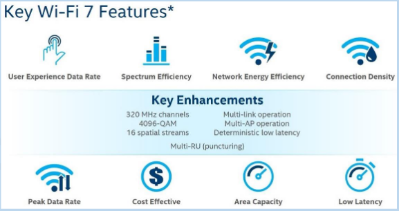
WiFi 7 New Features
WiFi 7 introduces several groundbreaking features designed to significantly enhance wireless performance:
Multi-Link Operation (MLO): This feature allows devices to simultaneously connect to multiple frequency bands, improving data throughput and reducing latency
Multi-RU (MRU) and Preamble Puncturing: These techniques optimize spectrum utilization, enabling more efficient data transmission and reduced interference.
6GHz 320MHz Channel Support: The wider channels in the 6GHz band allow for greater data transfer rates, significantly boosting network capacity.
4K-QAM Modulation: This advanced modulation technique increases data density, providing up to 20% more data throughput compared to WiFi 6.
Applications and Possibilities
With these innovations, WiFi 7 opens up new horizons for various applications:
4.8x Faster Speeds: Experience lightning-fast data rates that redefine what’s possible in high-bandwidth applications, from streaming 8K video to ultra-responsive online gaming.
5x Capacity: The increased capacity ensures more devices can connect simultaneously without compromising performance, perfect for dense environments like stadiums and smart cities.
Ultra-Low Latency: Achieve near-instantaneous communication ideal for real-time applications such as virtual reality, augmented reality, and mission-critical IoT systems.
524WiFi WiFi 7 Solutions
At 524WiFi, we offer two robust WiFi 7 solutions designed to meet diverse needs:
We are using the prerelease firmware with AB21 now. Very stable, can support DUAL SIM (Dual LTE module) applications well. Unfortunately can not support WiFi6 modules. This is the next goal for developers. Also the current QFirehose that rooter use is too old, so if you need upgrade firmware of your Quectel module, then we recomend to use X-WRT firmware and install the plug in to upgrade the firmware – QFirehose.
This firmware can support latest Quectel and SIMCOM 5G modems like RM510x, RM520x, RM530x, SIM8262E-M2 and more
We like the X-WRT firmware performance. X-wrt fully support wifi6 ( Mediatek MT 7915 / 7916 chipset supported), has full HW-NAT support WWAN and wifi6. Support dual-lte or 5G modem load-balance , see instructions bellow. This new fw also has introduce new Quectel QMAP protocol , it will reduce the cpu load! You can use this protocol for all 5G Quectel modems.
Attention – X-wrt default IP address is http://192.168.15.1/ username admin password admin. Default X-WRT information: SSID:X-WRT_XXXX. SSID Password:88888888.
It also supports the new RM520N-GL. But it not have auto configuration for LTE modems (Rooter firmware has it only). You need manual create new interface (QMAP cellular) and manual choose AT port to display modem signal information. Please see it in instructions bellow.
And how to set up the load balance for for two LTE modems and two SIM cards at H721 router?
First you need install 2 modems at M.2 and Mini-picie slot and sim cards, this example use RM502Q-AE and EP06 modems
Normally Mini-pcie modem will power up first and M.2 modem will power up secondly . So system will create Modem subsystem In sequence. That is to say, CDC-wdm0 & ttyUSB0 ttyUSB1 ttyUSB2 is Mini-pcie modem, CDC-wdm1 & ttyUSB3 ttyUSB4 ttyUSB5 is M.2 modem.
Delete all usbwan* at Network-interface
save & apply
Open network-Xwan, check enable xwan, set 3 at Number of xwan, check Auto balanced setup , set ip 8.8.8.8 at Tracking hostname or IP address IPv4 and IPv6 at Internet Protocol
save &apply
Wait for 30 second, network-interface change xwan01 general settings Protocol QMAP Cellular switch protocol Modem device /dev/cdc-wdm1 (M.2 modem) input your apn and related info. Advance settings. Set Use gateway metric 801 . Firewall settings.
Setup xwan02. pay attention, modem device /dev/cdc-wdm0(Mini-pcie modem) and metric use 802
Save and apply admin
After you finish settings, you can check the Mwan status at status-MultiWAN Manager
You can also set more at network-MultiWan Manager, such as Wan priority at Member Metric
.
.
Czech language instructions :
1. síť, rozhraní, odstranit všechna rozhraní usbwan** uložit a použít nastavení
2. síť, multi-dial, zapnout multi-dial, 3-dial sledování hostitele zachovat bránu, ostatní odstranit, protokol vybrat ipv4 a ipv6 uložit a použít nastavení
An APN (Access Point Name) is the gateway configuration that tells your cellular module which network path to use when connecting to the internet or a private data network. Think of it as the “address” your device hands to the carrier to establish a data session. It determines routing, IP assignment, and in many cases, what security policies apply to your traffic.
APNs exist because carriers need to route data traffic to different destinations: a consumer browsing social media, a fleet vehicle reporting GPS, and a medical device uploading readings all have very different requirements – and the APN is how the network tells them apart.
In IoT deployments, leaving the APN on auto-detect is a common mistake. Manually setting it ensures your device consistently connects to the right context, especially critical when using IoT SIMs, private APNs with fixed IPs, or roaming SIMs where auto-selection can land you on a suboptimal or even incorrect bearer. A wrong or missing APN means no data, silent failures, and hours of debugging that could have been avoided with a single AT command.
How to set “my APN” in a cellular module?
By default, cellular modules come without a pre-defined APN (Access Point Name). It is however best practice to set this to the correct value to tell the module how to get online
AT+CGDCONT=1,"IPV4V6","techship.com" // Set APN
OK
AT+CGDCONT? // Query APN
+CGDCONT: 1,"IPV4V6","techship.com","0.0.0.0.0.0.0.0.0.0.0.0.0.0.0.0",0,0,0,0,,,,,,,,,,"",,,,0
AT+CFUN=1,1 // Restart the module for settings to take effect
Via Windows GUI:
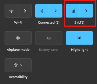
The connection manager settings and controls can be found and accessed on Windows desktop start menu through the network icon (see picture)
The Cellular tab can be found in Windows system settings and the connection APN details can be manually entered through “Advanced options”
Via Linux ModemManager/NetworkManager:
Using NetworkManager and ModemManager in Linux to automatically establish a connection and configure IP details
In this article we will show how to set up NetworkManager to automatically configure, establish the cellular data connection in your system.
NetworkManager and ModemManager are open source tool for Linux to manage several types of networks and interfaces such as ethernet, wifi, etc. It can also manage cellular WWAN interfaces through the ModemManager tool. It is hosted by the Freedesktop.org community and driven by Aleksander Morgado and other contributors. please visit https://wiki.gnome.org/Projects/NetworkManager and https://www.freedesktop.org/wiki/Software/ModemManager/ for latest information, source code, API reference manuals, debugging tips, contribution, mailing list etc.
ModemManager is capable of communicating over several types of device control channels such as QMI/RMNET, MBIM, MODEM / AT command etc. But support for vendor proprietary or out-of-kernel drivers are none or very limited. Such drivers are gobinet, simcom_wwan and other drivers provided by the vendors directly.
Many Linux distributions have NetworkManager and ModemManager pre-installed or they can typically easily be installed through the systems package manager. In Ubuntu for example apt can install it for you by command if not already installed: apt install network-manager
Check with commands below that you have both tools installed in system and their versions. NetworkManager -V ModemManager -V
ModemManager (and NetworkManager) are continuously developed for better compatibility with the cellular devices, therefore it is recommend to use a recent version of the tools and in case of problem situations, evaluate the latest versions from source and check the mailing list archives for possible discussions on the problem experienced.
Keep in mind that NetworkManager and ModemManager projects are not directly developed or driven by the cellular device vendors and the compatibility with the device you aim to use can be limited. Some vendors contribute with code to make their devices fully compatible, while others don’t. Many cellular devices can be set to expose standardized types of USB network interface and control channel such as MBIM interface by USB-IF or the Qualcomm proprietary interface QMI that ModemManager will try to identify, and often manage to work successfully with but there are exceptions also.
Both NetworkManager and ModemManager have command line interfaces (nmcli and mmcli respectively) where you can interact with the management tools.
Have ModemManager list all the cellular device it has detected. Here we use the Alcatel IK41 series with MBIM interface in this example: mmcli –list-modems /org/freedesktop/ModemManager1/Modem/0 [Alcatel] Mobilebroadband
Check that the cellular device is managed by NetworkManager by not having state “unmanaged” listed for it. nmcli device status DEVICE TYPE STATE CONNECTION cdc-wdm0 gsm disconnected — enp3s0 ethernet unmanaged — lo loopback unmanaged —
Now you should create a connection profile in NetworkManager for your specific network carrier and SIM card with the “nmcli connection add” command: For example: nmcli connection add type gsm ifname ‘*’ con-name ‘3-sweden’ apn ‘data.tre.se’ connection.autoconnect yes gsm.pin 0000
– type is gsm for all typical cellular connections unless it is of cdma type. – ifname is the control interface name, in this case cdc-wdm0, wildcard can be used also to have it autoselect. – con-name is the profile name you want to give it. – apn is provided by your network carrier and tells the modem what attach point it should use for the data connection. – connection.autoconnect set to yes will make NetworkManager always try to auto connect and maintain this profile connection. – gsm.pin lets you provide a pin code for the SIM card, that NetworkManager will try to use if PIN check is enabled for SIM card.
There are several additional commands and attributes available such as username and password settings for the APNs etc. Refer to the NetworkManager help and manual pages for full details on the commands.
If successful you should receive a reply similar to this one: Connection ‘3-sweden’ (cad6fcbf-2cb1-4796-b7e6-67b9f9635aef) successfully added.
You can check the status now by command: nmcli device status DEVICE TYPE STATE CONNECTION cdc-wdm0 gsm connected 3-sweden enp3s0 ethernet unmanaged — lo loopback unmanaged —
Where connected should be listed as state if the connection establishment was successful.
If the connection is not successful or you want more details about the device and connection you can check commands:
You can list the current status with command: nmcli radio WIFI-HW WIFI WWAN-HW WWAN enabled enabled enabled enabled
nmcli connection show NAME UUID TYPE DEVICE 3-sweden e946017f-2e9c-477b-89ad-4c31e7331d65 gsm cdc-wdm0
Ifconfig should now show the related IP address details already set to the network interface by NetworkManager: ifconfig wwan0: flags=4291 mtu 1500 inet 2.68.73.130 netmask 255.255.255.252 broadcast 2.68.73.131 inet6 2a02:aa1:1017:6d11:6474:7254:7b72:eb09 prefixlen 64 scopeid 0x0 inet6 2a02:aa1:1017:6d11:1060:3dff:feac:e92f prefixlen 64 scopeid 0x0 ether 12:60:3d:ac:e9:2f txqueuelen 1000 (Ethernet) RX packets 186 bytes 10886 (10.8 KB) RX errors 0 dropped 0 overruns 0 frame 0 TX packets 5 bytes 480 (480.0 B) TX errors 0 dropped 0 overruns 0 carrier 0 collisions 0
You can now for example test the connection over the network interface by sending ping requests. Testing IPV4 connection: ping -4 -I wwan0 8.8.8.8 PING 8.8.8.8 (8.8.8.8) from 2.68.73.130 wwan0: 56(84) bytes of data. 64 bytes from 8.8.8.8: icmp_seq=1 ttl=118 time=55.8 ms 64 bytes from 8.8.8.8: icmp_seq=2 ttl=118 time=45.4 ms 64 bytes from 8.8.8.8: icmp_seq=3 ttl=118 time=42.9 ms — 8.8.8.8 ping statistics — 3 packets transmitted, 3 received, 0% packet loss, time 2003ms rtt min/avg/max/mdev = 42.918/48.053/55.845/5.601 ms
Testing IPV6 connection: (if your cellular device, network subscription and APN supports it) ping -6 -I wwan0 2600:: PING 2600::(2600::) from 2a02:aa1:1017:6d11:1060:3dff:feac:e92f wwan0: 56 data bytes 64 bytes from 2600::: icmp_seq=1 ttl=46 time=172 ms 64 bytes from 2600::: icmp_seq=2 ttl=46 time=171 ms 64 bytes from 2600::: icmp_seq=3 ttl=46 time=169 ms 64 bytes from 2600::: icmp_seq=4 ttl=46 time=168 ms — 2600:: ping statistics — 4 packets transmitted, 4 received, 0% packet loss, time 3004ms rtt min/avg/max/mdev = 167.921/170.037/172.272/1.651 ms
The connection is successful and automatic reconnect is working when testing to unplug and plug in the device again. For additional configurations, commands and available attributes, please relate to the manual pages for NetworkManager and ModemManager.
Troubleshooting logs: NetworkManager and ModemManager write log messages to the Linux syslog file /var/log/syslog. In case of problems with establishing a cellular data connection, please copy the logfile after the problem have appeared and include it in a Techship technical support ticket.
In some situations more detailed debug logs are needed, these can be acquired by changing the log levels for NetworkManager and ModemManager and run them manually.
To capture debug logs, please first disable and stop the normal services: systemctl stop NetworkManager ModemManager systemctl disable NetworkManager ModemManager
Run them manually in background with debug level set: /usr/sbin/ModemManager –log-level=DEBUG &> /dev/null & /usr/sbin/NetworkManager –log-level=DEBUG &
Reproduce the cellular data connection problem. Once completed, kill the processes: killall -TERM NetworkManager ModemManager
Copy the relate messages in syslog to a mm-nm-sys-debug.log logfile: grep -E ‘ModemManager|NetworkManager|systemd|dbus-daemon|dhclient’ /var/log/syslog > mm-nm-sys-debug.log
Activate and start the services again: systemctl enable NetworkManager ModemManager systemctl start NetworkManager ModemManager
Include the mm-nm-sys-debug.log in a technical support ticket at Techship.com where you describe the issue in details and include other relevant information also such as kernel version, ModemManager and NetworkManager versions, dmesg log etc.
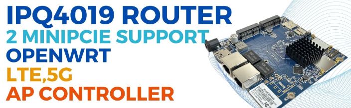
Empowering Customization and Connectivity: The IPQ4019-Based Industrial Board
In the realm of industrial connectivity, adaptability reigns supreme. Introducing the IPQ4019-based industrial board, a versatile solution engineered to offer unparalleled customization and connectivity options. Let’s explore its key features:
Tailored Dual LTE Support
– This board supports customizable configurations for dual LTE support, allowing for routerboard/baseboard+SOM setups tailored to specific requirements. Whether it’s optimizing bandwidth or ensuring redundancy, users can fine-tune their connectivity solutions with ease.
Efficient Network Segmentation via VLANs
– Recognizing the importance of network segmentation, this board seamlessly integrates VLAN support. Users can create distinct virtual networks within a single physical infrastructure, enhancing security and efficiency.
Customized LUCI Interface
– Elevate brand identity and user experience with a customized LUCI interface featuring the customer’s logo. This personalized touch adds a professional flair while maintaining familiarity for end-users.
Extended Range Firmware Customization
– Break through geographical barriers with custom firmware designed for long-distance transmission, reaching up to 20km. Whether it’s remote installations or expansive deployments, rest assured that firmware updates will reach even the most remote endpoints.
Seamless Integration with Leading Controllers
– Integrate effortlessly into existing network architectures with support for Wallys AP Controller and TIP Cloud Controller. Benefit from centralized management, configuration, and monitoring capabilities, enhancing operational efficiency and scalability.
Conclusion: Unmatched Flexibility for Industrial Connectivity
In conclusion, the IPQ4019-based industrial board stands as a beacon of innovation and adaptability in industrial connectivity. With its support for customizable LTE configurations, VLANs, branded interfaces, long-distance firmware transmission, and integration with leading management controllers, this board offers unparalleled flexibility and connectivity options. Whether optimizing performance, enhancing security, or streamlining operations, this versatile solution is poised to revolutionize industrial connectivity challenges.
DR4019 / DR4029
Featuring with industrial-grade IPQ4019/IPQ4029 chipset
Integrated with 2x 2 5G high power Radio module and 2×2 2.4G high power Radio module
Support 4.940GHz to 5.825GHz Frequency Range
Support 2.400GHz to 2.482GHz
Support 2 x 5G MMCX Connectors and 2×2.4G MMCX
Support 5MHz/10MHz/20MHz/40MHz/80MHz Bandwidth
Support 11ABGN/AC
Support fixed data rate
RoHS compliance ensure a high level protection of human health and the environment from risks that can be posed by chemicals
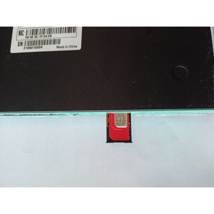
Put a functional SIM card into the SIM slot (please see picture bellow).
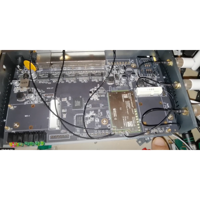
Please bear in mind that there are 2 types of antennas: LTE and WiFi. Be sure that you’re putting in the right antenna to the right slot, You can recognize them by female and male connectors.
After ensuring that everything is in the right place, please first connect your LANport then the routers DC interface, please use 12V / 2A power adapter.
Now type into your browsers URL query “192.168.1.1” it’ll take you to the routers firmware
Passwords are: Viper firmware “Password1234” or “admin” for OpenWRT
WiFi default password: Viper firmware “LakeWater561” , in OpenWRT firmware is WiFi without encryption by default.
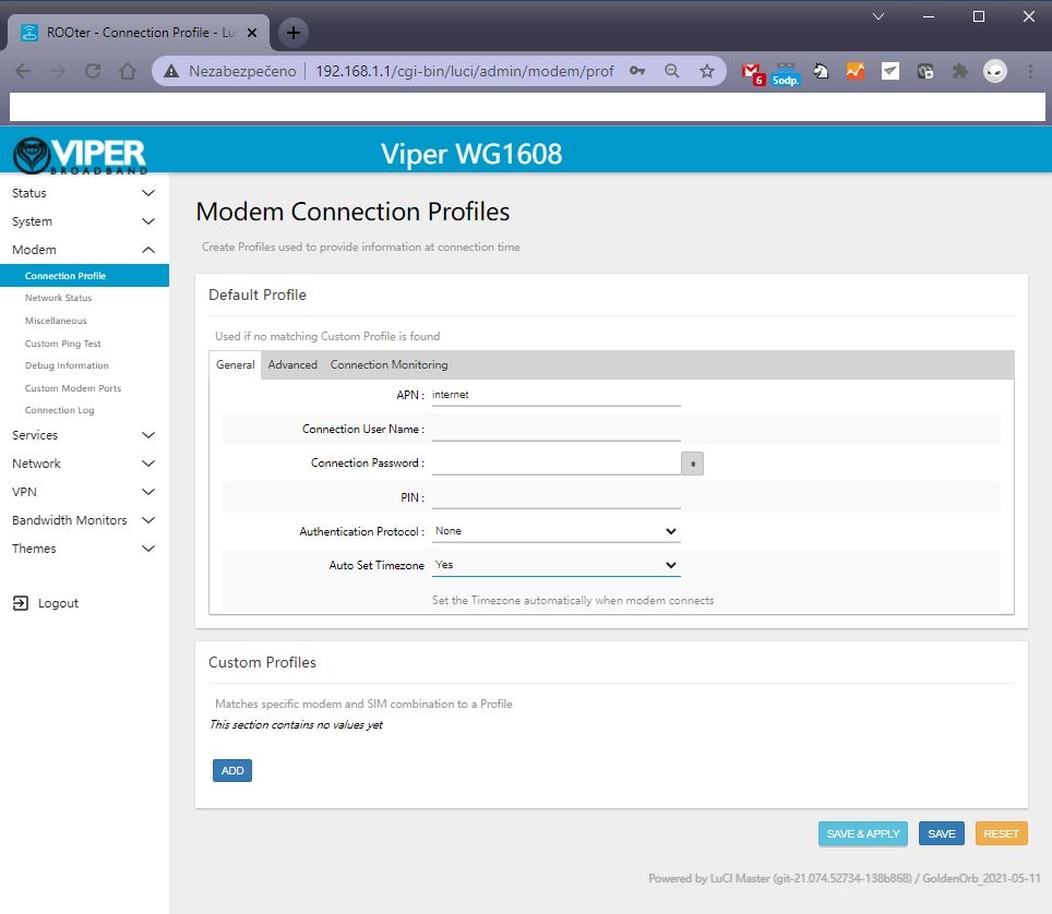
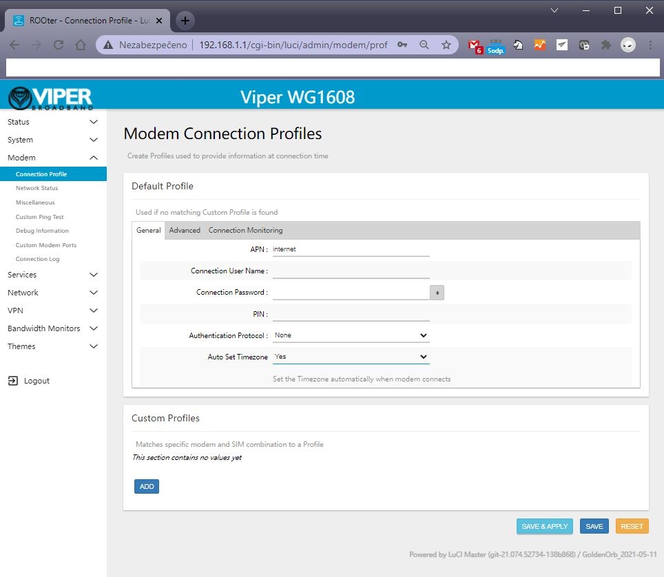
After getting inside your firmware please go to “Modem > Connection profile” and set your APN to “internet” or other APN from your provider and wait at least 5 minutes.
A few of the more common carrier APNs are listed below:
Don’t forget to check “Modem > Network Status” to see if your router recognizes:
Your SIM card
Your modem
Strength of your signal
If you see every mentioned option in No. 6 then congratulations!!! Your router is ready to be deployed. We hope that this user manual was helpful. We’re trying to keep it as simple as humanly possible.
We set customers own specific settings as long as they’re mentioned in the order note.
If you have any more questions, please be sure to contact us at [email protected].
ADVANCED SECTION
QUECTEL RM520N-GL, RM502Q AND OTHER QUECTEL MODULE SETUP IN OPENWRT FIRMARE :
1 – go to the Network – Interfaces – 4G menu and check the 4G/5G module button , then you can set the APN
2 – Then save and reboot and you can see 4G/5G connected in Status page :
Please insert your 4G or 5G LTE card in “M.2 LTE card slot”
Connect your pigtails to your LTE card and your WiFi card (If there’s a right slot for it marked with “WiFi” text)
A) is the correct way.
B) This one isn’t as this may result in damaging contact between the LTE card and antenna.
This tutorial will demonstrate the build and configuration process for the M2M 5G LTE H721 Dual Modem Router.
2023 note : This popular router can support new popular 5G modules like Quectel RM502 Q, RM520N or Sierra Wireless 5G modems. New switch just for Sierra Wireless EM919x and EM7690, these card default work at PICE mode. We add new switch just let EM919x EM769x work at USB mode. Please see this video : https://www.youtube.com/watch?v=whKcn4SFMKQ
1 – New firmware has support AW7916 / AW7915 wifi 6 modules. Do not support QCN wifi 6.
2 – It supports RM520N-GL. X-WRT soft engineer use RM520N . You need manual create new interface (QMAP cellular) and manual choose AT port to display modem signal information
3 – New fw has introduce new Quectel QMAP , it will reduce cpu load.
4 – Full support hw-nat, 5 – Support dual-lte or 5G modem load-balance (see instruction.)
The modem signal Luci is still in development.
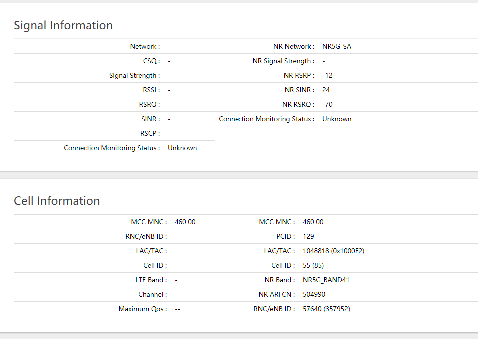
Please note, Wodaplug ( 524wifi.com ) are using V7 unique rebuild version of this popular modem for full 5G equiped with protection, pls note – some pictures of older versions may be not coresponding to your newer model. Good new also is that we just finish 5G_NR signal status page and Simcom 8200 5G modem support.
5G Signal information displayed by our router
There are many possible build variations for building the M2M. Autor decided to use a single EM7565 CAT12 M.2 modem and dual mini PCI-E WiFi cards—one for 2.4GHz and the other for 5GHz WiFi.
The WiFi cards used in this build are dual band cards, but each card may only operate on one band at a time—either 2.4GHz or 5GHz. The QCA AC WiFi card will work well for its higher speed capabilities on the 5GHz WiFi, while the Atheros WiFi card will handle the 2.4GHz WiFi. New firmware support Ath10k 802.11AC Wave2, about 20% improvement at Wifi 5.8G support QCA9984 QCA9886 QCA9888
The components used for this particular build are:
(1) Small Phillips Head Screwdriver (1) Small Standard Head Screwdriver (1) 5/16 Nut Driver, Socket or Wrench (1) Wooden Chopstick with Tip Sanded Flat (or similar object to use for connector attachments)
OPENING THE ROUTER CASE:
There are seven screws in total to remove before separating the router case. This is required to obtain access to the router PCB to install the Modem, WiFi Cards and Pigtail connectors.
Place the router on a flat table or surface with the lower case decal facing up.
Remove the three screws along the upper edge.
Remove the two screws from each side of the router.
After removing all seven screws, carefully slide the lower case back about an inch from the upper case.
Hold the lower and upper case in their position and carefully flip the router into its upright position.
Remove the Upper Case from the router assembly to expose the PCB (Printed Circuit Board).
The EM7565 is be mounted in the M.2 interface slot labeled #3
The 5 Volt WiFi Card is to be mounted in the Mini PCI-E interface slot labeled #2 since it supports both 3.3 and 5 Volt WiFi Cards.
The Atheros WiFi Card is to be mounted in the Mini PCI-E interface slot labeled #1
(Note: The M.2 interface slot #4 on the underside of the PCB for a second modem is not being used for this build).
Carefully slide each of the modem and WiFi cards into their proper interface slot—paying special attention to the proper key/pin alignments—and secure each of the cards in place with the screws that are included (shown in the red circles):
INSTALLING THE ANTENNA PIGTAIL CONNECTORS
There are 12 different antenna cutouts and plastic plugs that should accommodate most any antenna configuration. Decide what antenna placements work best for a particular build.
Below is the antenna configuration used for this build which works rather well.
Remove the plastic plugs from both upper and lower case to be used for the antennas.
Place each of the WiFi RP-SMA and Cellular (LTE) SMA antenna pigtail connectors into their proper cutout slot.
Consideration should be given as to the length of cable being used in relation to the location of the WiFi card or modem it will be connected to.
Notice that the SMA and RP-SMA antenna connectors appear similar, but they are different. One is not compatible with the other. Generally, WiFi uses RP-SMA while cellular uses SMA. The differences can be seen on the following image:
Place the star and lock washers over the connector and secure in place with the nut. Use the 5/16 nut driver to snug the connector nut—but do not over-tighten.
Now the modem and WiFi cards are installed and secured in place with their screws, and the pigtail connectors are installed in the upper and lower case, it is time to install the pigtail’s U.FL and MHF4 connectors to the cards.
Care must be exercised when working with these connectors to avoid damaging the tiny connectors or ports on the modem. Good lighting is crucial and a magnifying glass will be extremely useful.
When connecting these connectors, make certain they are flat and aligned perfectly with the connector port of the modem. A flat instrument placed on top of the connector (the wooden chopstick in this example) will help to snap the connector evenly in place.
Do not force the connects. If they do not snap/pop into place with slight downward pressure, chances are the connector and port are not aligned.
Once the connectors are installed, the Selector Switch on the PCB must be set for this particular configuration. According to the documentation, when using the M.2 slot #3 for the modem, and a WiFi Card in the Mini PCI-E slot #1, the Switch should be in the down position:
Switch selector (optional – depends on model – wodaplug.com new V5G version does NOT have switch)
Confirm the switch is in the down position (for older HW versions only):
The Upper and Lower cases may now be reassembled and secured with the seven screws.
The antennas may also be installed in their proper positioning.
CONFIGURING ROUTER WITH GOLDENORB
The M2M NEXG H721 Dual Modem Router comes with GoldenOrb firmware preinstalled which helps to simplify the overall router build and configuration.
Plug the 12 Volt power supply into the power plug on the router.
Connect an Ethernet cable from one of the LAN ports on the router to the Ethernet plug on the PC.
(Note which SIM Card slot will be used for the EM7565 but DO NOT install the SIM Card until after GoldenOrb is configured and ready to connect to the internet).
1. LAN – SIM – Power
Once the M2M router has booted up, open a web browser and enter 192.168.1.1 in the address bar and press enter. The Splash Page should appear. Click on the “Router Login”:
2. Router splash page
Log into the router using the default user name “root” (without the ““marks) and the default password of “admin”.
The default user name and password is located on the decal on the bottom of the router.
Default WiFi passwords – for older firmare version it was “12345678” , new Rooter firmware version use “rooter2017” as default WiFi password.
3. Router Login
Once logged in, the Overview screen should appear.
4. Overview screen
From the left side tabs, select System > System > General Settings.
Use the Time Zone down arrow and select the proper time zone.
Click on the Sync With Browser button.
Click Save and Apply.
(Important, any change in a GoldenOrb setting must be Saved and Applied to implement and remember the change).
5. Time zone
Go to Modem > Connection Profile > General > APN
APN stands for Access Point Name, which is required to identify and connect to a specific cellular carrier. Each carrier uses a different APN.
Type the correct APN used by your cellular carrier that is tied to the SIM Card and plan to be used in the M2M router.
Click on Save & Apply.
A few of the more common carrier APNs are listed below:
Go to System > Administration > Router Password and enter a password that will be used to log into GoldenOrb.
Some may prefer to skip this step and leave the default password of “admin”. This may be changed after all of the other configurations are made and the router is connected to the internet.
7. Setting login password
It is now time to configure the WiFi. Go to Network > Wireless.
The Wireless Overview screen will appear and show the WiFi cards installed in the router. In this build, Radio0 is the Atheros card used for the 2.4GHz WiFi network.
Click on the Radio0 Master tab at the top left of the screen.
8. Select Wireless Network Radio0
Select the Mode and Channel that the 2.4GHz network is to operate on.
In this case, N is selected for the Mode and Channel 11 is used since it has little traffic on that channel.
The Channel can be changed to another channel if the one selected becomes too congested.
There are WiFi analyzer apps that can be downloaded onto your smart phone to assist in selecting the best, non-congested channel available at your location.
Enter the ESSID that the 2.4GHz WiFi Network will be named. In this build TestHome was used.
9. Configure Atheros Radio0 2.4GHz 1
Click on the Wireless Security tab in the lower part of the Interface Configuration screen.
Select the Encryption to be used by selecting the down arrow. In this case WPA2-PSK is selected.
Under Key, enter the Password that will be used to Log onto the 2.4Ghz WiFi Network.
Click Save & Apply to save setting.
Next is to configure the 5GHz WiFi. Go to Network > Wireless and select the Radio1 Master from the top of the menu.
Radio1 is the Complex card used in this build.
11. Select Wireless Network Radio1
Select Mode and Channel that 5Ghz WiFi network is to operate on.
In this case, AC for the Mode and Channel 36 was selected since there is little traffic on this channel. This can be changed to another channel if this one becomes too congested.
Again, a WiFi Analyzer app will help make the proper selection.
Enter the ESSID that the 5GHz WiFi Network will be named. In this case TestHome5G was used.
12. Configure WiFi Radio1 5GHz 1
Click on the Wireless Security tab in the lower part of the Interface Configuration screen.
Select the Encryption to be used by selecting the down arrow. In this case WPA2-PSK is selected.
Under Key, enter the Password that will be used to Log onto the 5Ghz WiFi Network.
Click Save & Apply to save setting.
Default WiFi passwords – for older firmare version it was “12345678” , new Rooter firmware version use “rooter2017” as default WiFi password.
13. 5GHz WiFi Password and Encryption
Optional: For users who may have limits imposed by their carrier on the amount of hotspot data that may be used on a monthly basis, my want to use the TTL custom settings.
Go to Network > Firewall > Custom TTL Settings (top of the screen) > Enable > set to 65 > Save & Apply.
14. TTL Settings
Assuming all of the settings are properly configured, you should now be ready to connect to the internet. Unplug power from the router, install an activated SIM Card, plug the power back in and give it a minute or two to connect.
1 – New firmware has support AW7916 / AW7915 wifi 6 modules. Do not support QCN wifi 6.
2 – It supports RM520N-GL. X-WRT soft engineer use RM520N . You need manual create new interface (QMAP cellular) and manual choose AT port to display modem signal information
3 – New fw has introduce new Quectel QMAP , it will reduce cpu load.
4 – Full support hw-nat, 5 – Support dual-lte or 5G modem load-balance (see instruction.)
WiFi 7 in Q1-Q2 2024 – QCN 9574 boards and QCN 9274 / 6274 DBDC radio modules available for testing now !
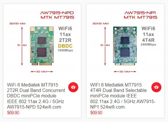
QCN 9074 / 9024 / 6024 WiFi 6 / 6E 11ax 4×4 WiFi Modules and new Mediatek MT7915 / 7916 Wi-Fi 6 / 6E miniPCIE modules available now and tested successfully for mas production!
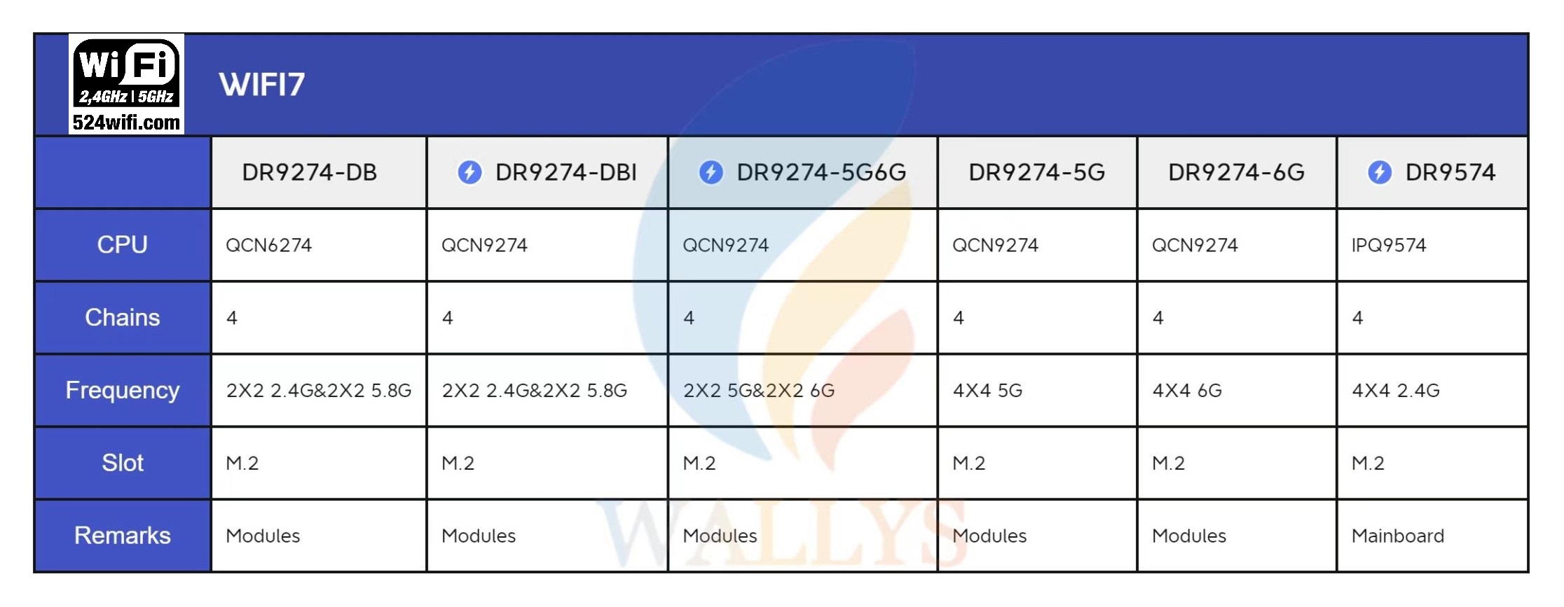
524WiFi the pioneers in connectivity solutions, introduces an array of advanced WiFi 7 modules designed to cater to diverse needs. Let’s delve into the details of 524WiFi WiFi 7 modules and compare their specifications through informative data sheets.A Quick Overview
1.DRiver 9274-5G|QCN9274/QCN6274 WIFI7 SINGLE BAND 5G
Tailored for single-band 5G applications,Powered by Qualcomm’s QCN9274 ‘Waikiki’ series,Features 4×4 MU-MIMO and supports up to 4096-QAM,Operating temperature ranges from -20°C to 70°C for commercial grade and -40°C to 85°C for industrial grade
Key Feature:
Qualcomm Atheros QCN9274 for Industrial Grade;
Qualcomm Atheros QCN6274 for Commercial Grade;
Maxim Tx power 20dBm per chain;
4×4 5G MU-MIMO, up to 5765Mbps physical data rate;
Support up to 4096-QAM;
M.2 connector;
PCI Express 3.0 Interface
2.DRIVER 9274-6G|QCN9274/QCN6274 WIFI7 SINGLE BAND 6G
Specifically designed for single-band 6G requirements,Utilizes Qualcomm’s QCN6274 ‘Waikiki’ series for robust performance,Boasts a 4T4R (4×4) MU-MIMO 6GHz solution,Achieves up to 11.530Gbps with 4 spatial streams.
Key Feature:
Qualcomm Atheros QCN9274 for Industrial Grade;
Maxim Tx power 22dBm per chain;
4×4 6G MU-MIMO, up to 11530Mbps physical data rate;
Support up to 4096-QAM;
M.2 connector;
PCI Express 3 .0 Interface
3.DRIVER 9274-DB|QCN9274/QCN6274 WIFI7 DUAL BAND DUAL CONCURRENT-2.4G&5G
Perfect for dual-band, dual-concurrent operation in both 2.4G and 5G,Employs Qualcomm’s QCN6274 ‘Waikiki’ series for exceptional connectivity,Supports both Access Point (AP) and Station (STA) modes simultaneously
Key Feature:
Qualcomm Atheros QCN6274;
Qualcomm Atheros QCN9274 for Industrial Grade;
Maxim Tx power 20dBm per chain;
2×2 2.4GHz MU-MIMO, up to 1376Mbps physical data rate;
2×2 5GHz MU-MIMO, up to 5765Mbps physical data rate;
Support up to 4096-QAM;
M.2 connector;
PCI Express 3 .0 Interface
4.DRIVER 9274-5G6G|QCN9274/QCN6274 WIFI7 DUAL BAND DUAL CONCURRENT-5G&6G
Tailored for dual-band, dual-concurrent operation in 5G and 6G frequencies,Utilizes Qualcomm’s QCN9274 ‘Waikiki’ series for reliable performance,Wide signal coverage with a 5V design
Key Feature:
Qualcomm Atheros QCN9274 for Industrial Grade;
Maxim Tx power 22dBm per chain;
2×2 5G & 2×2 6G MU-MIMO, up to 8,647Mbps physical data rate;
Support up to 4096-QAM;
M.2 connector;
PCI Express 3 .0 Interface
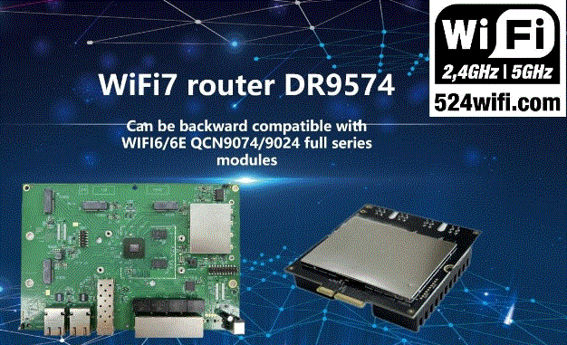
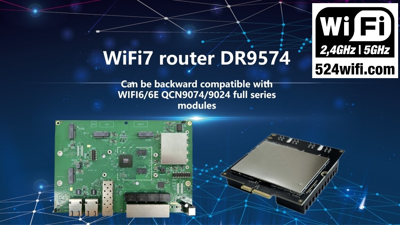
5.WIFI7 PLATFORM DRIVER 9574-IPQ9574
Support 11ax 2.4G 4×4 radio on board
A robust platform featuring the Qualcomm IPQ9574 or IPQ9554
Designed specifically for WiFi 7 applications Industrial
Backward compatible with WiFi6/6E QCN9074 QCN9024 full series modules
524WiFi WiFi 7 modules are engineered for versatility and reliability, making them ideal for Enterprise, Industrial, Cybersecurity, Transportation, and SMB applications. The modules support Multi-Link Operation (MLO) for reduced latency, Preamble Puncturing for improved spectral efficiency, and unique features like FIPS L2 for enhanced cryptographic protection.
Wi-Fi 7 samples from Compex available for orders
The latest Wi-Fi standard is brought to market by Compex with the new WLW7000 series, based on Qualcomm’s QCN6274 or QCN9274 chipsets for commercial and industrial versions respectively. The 5V design enables wider signal coverage along with all the benefits of the new standard such as preamble puncturing. The new series comes in 4 different configurations with one Dual-Band-Dual-Concurrent on the 2.4/5 GHz bands as well as 3 Single-Band versions for 2.4/5/6 GHz respectively, with the 6 GHz verison reaching theoretical speeds of over 11.5 Gbps.
WHAT’S WI-FI 7?
WI-FI 7 HAS THE FOLLOWING FEATURES:
– provide over 3 times faster data rates of 46 Gbps using a 320 MHz channel in the 6 GHz – one 160 MHz channel in the 5 GHz band with up to 4096-QAM (4K-QAM) modulation – 16 spatial streams MU-MIMO,
– New Multi-Link Operation (MLO) enables Wi-Fi 7 to combine several frequencies across bands into a single and steady connection.
Wi-Fi 7 is being designed to be optimized for these video applications like gaming, streaming, smart home devices and services, cloud computing, video conferencing , etc.
WI-FI 6E/7 COMPARISON
WI-FI 6E
IEEE 802.11ax Frequency 2.4GHz, 5GHz, 6GHz Channel bandwidth 160 MHz QAM 1024-QAM 4096-QAM Theoretical maximum speed 9.6 Gbps Spatial streams 16×16 MU-MIMO Application Ac cess point, high quality video streaming, etc.
WI-FI 7
802.11be EHT
Frequency 2.4GHz, 5GHz, 6GHz
Channel b-QAM
Theoreticaandwidth Up to 320 MHz
QAN 4096l maximum speed 46 Gbps
Spatial streams 16×16 MU-MIMO
Video applications like gaming, streaming, smart home devices, cloud computing, video conferencing, etc.
2023 NEW PRODUCTS – WIFI 7 QCA AP AND CLIENT SOLUTIONS FROM SPARKLAN:
MEDIATEK WIFI 6 MINIPICE MODULES BASED ON MT7915 CHIPSET WITH WIDE LINUX AND OPENWRT DRIVERS SUPPORT
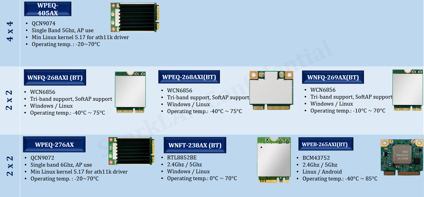
QCN9074 VS QCN9024 | WIFI6E IOT 4X4 TRIBAND 2.4G 5G 6G NETWORK CARD AND APPLICATION
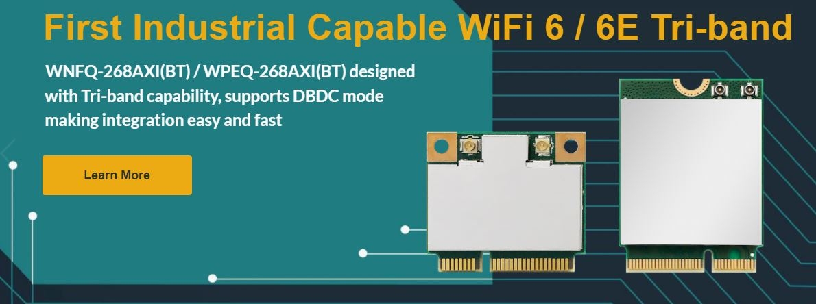
WHAT ARE THE APPLICATIONS OF AN INDUSTRIAL TRI-BAND NETWORK CARD SUPPORTING 2.4GHZ, 5GHZ, AND 6GHZ?
Imagine the boundless possibilities that come with an industrial Tri-Band network card, seamlessly embracing the 2.4GHz, 5GHz, and lightning-fast 6GHz frequency bands. Here’s a glimpse into the exciting realms of its potential applications:
1. Smart Manufacturing & IoT Revolution: In the heart of smart manufacturing, these Tri-Band cards orchestrate a symphony of devices. From factory robots to floor sensors, they unite the Internet of Things (IoT) to make real-time data analytics and intelligent production a reality.
2. Robotic Precision & Automation: When it comes to industrial robots and automated machinery, precision and speed are paramount. Tri-Band network cards deliver high-speed data transfers and unwavering connections, ensuring uninterrupted automation.
3. Surveillance with Clarity: Industrial sites demand top-tier security. Tri-Band cards support high-definition video streams, fortifying security systems. They extend the eyes and ears of surveillance networks, enhancing vigilance.
4. Scientific Excellence: In the world of scientific research and high-performance computing, these network cards are the lifeline. They enable lightning-fast data transfer, facilitating experiments, simulations, and data analysis at astonishing speeds.
5. Connecting the Unreachable: When it’s about connecting distant devices in remote locations, Tri-Band cards are the bridge. They make remote monitoring, diagnostics, and maintenance a breeze, minimizing downtime.
6. Agriculture & Environmental Guardians: In the fields of agriculture and environmental monitoring, they enable large-scale sensor networks. These networks collect invaluable data for better decision-making, crop management, and environmental preservation.
7. Aerospace & Beyond: Think of satellite communications and aerospace ventures. Tri-Band cards empower high-speed data exchanges between spacecraft, satellites, and ground stations, venturing into the far reaches of the cosmos.
With the 6GHz band, an integral part of the WiFi 6E, industrial Tri-Band network cards offer an abundance of spectrum resources. They cater to the insatiable appetites of high bandwidth and low latency. The future of industrial connectivity shines brighter than ever before!
524WIFI 6E IOT 4X4 TRIBAND 2.4G 5G 6G NETWORK CARD:DR9074
Both the QCN9074 and QCN9024 are Qualcomm chips, and Wallys has chosen this platform for the development of Tri-Band card due to its exceptional stability and superior performance.
Let me share the fascinating story of its inception. Before the advent of the remarkable DR9074 Tri-Band Network card, Wallys had already pioneered single-band network cards like the DR9074-2.4G, DR9074-5G, and DR9074-6E, each earning a reputation for top-notch performance.
Then came an intriguing request from one of our valued customers: ‘The DR9074-5G and DR9074-6E deliver exceptional performance; do you have plans for a Tri-Band version of this card?’ As an innovation-centric company, this question ignited a spark among our engineers.
Fuelled by passion and driven by the pursuit of excellence, our engineers toiled day and night. And voilà, Wallys proudly presents the DR9074 Tri-Band Network card, a testament to our commitment to innovation and customer satisfaction.
Now, let’s dive into the exciting features of this groundbreaking card!
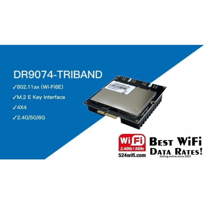
DR9074-TRIBAND
■ Qualcomm Atheros QCN9024
■ Maxim 23 dBm per chain,up to 4949Mbps
■ Data Rateup to 4949Mbps
■ Support Tri Band 2.4GHz&5GHz&6GHz 4×4 WiFi 6E (802.11ax)
■ 4 spatial streams (4SS)
■ M.2 E Key Interface
■ PCI Express 3 .0 Interface
Symbol/Parameter
Chipset:Qualcomm Atheros QCN9024
WLAN Host Interface:PCI Express 3.0 Interface
System Memory:2Mbit serial I²C bus EEPROM
Standard Operating Voltage:5V
Operating Systems:QSDK
Host Interface:M.2 E Key
Antenna Cable / Port:4 x MMCX Connectors,4T4R
Frequency Range:2.412GHz-2.472GHz & 5.18GHz-5.825GHz & 5.925GHz-7.125GHz
Data Rates for WALN:Maxim 23dBm per chain, up to 4949Mbps
Channel Spectrum Widths for WLAN:Support 20/40/80/160MHz
Get yourself some samples to test – availbe now ! Race towards the adoption of WiFi 6E in your wireless solution! – HOW WE MAKE QCA QCN9074 WLAN WIFI 6 MODULE DR9074 4X4 WORK ON X86 LINUX PLATFORM – PLEASE READ HERE.