DR5424S Design-In Checklist: 10G SFP, PoE, and M.2 E-key on a Qualcomm IPQ5424 Wi-Fi 7 Platform
A Wi-Fi 7 board looks simple on a spec sheet. The wireless platform is one line. The work that decides whether your product ships on time sits in the other lines: the uplink, the power input, the expansion slots, the heat, and the enclosure.
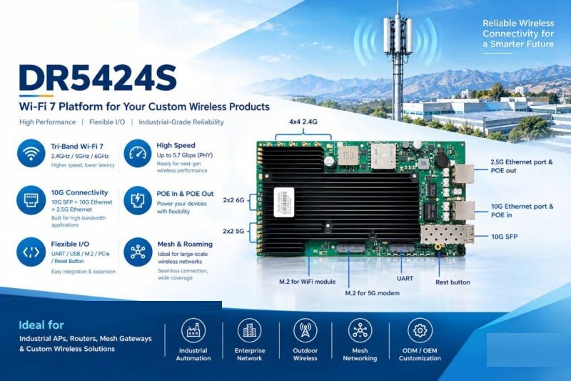
DR5424S is a tri-band Wi-Fi 7 platform built on Qualcomm IPQ5424. It shares its wireless platform with DR5424 but spends its interface budget differently: a 10G SFP uplink, 10GbE PoE input, 2.5GbE PoE output, and 2× M.2 E-key PCIe 3.0 slots, instead of a bank of RJ45 ports.
This article walks through what each interface changes in a real design, what to verify before committing, and where the board stops and system engineering begins.
What does DR5424S change in a product design?
Between DR5424 and DR5424S, the Wi-Fi 7 platform stays the same (Qualcomm IPQ5424). The wired side and the expansion side change.

For a product team, that is not a spec swap. It changes four parts of the product at once: how the device is cabled, how it is powered, how it is extended, and how it is cooled and housed. Each one has its own checks below.
Fiber uplink: 10G SFP
A 10G SFP port replaces a copper uplink with a cage that accepts a fiber module. That helps where nodes sit far from the backbone, as in industrial parks, warehouses, ports, and large facilities.
What to check:
- Module type and reach. The cage doesn’t decide your fiber type or distance. Choose the module for the deployment, then confirm it works on the board.
- Module compatibility. Test the specific SFP modules you plan to ship or recommend, not only one reference module.
- Module power and heat. An optical module adds heat inside or next to the enclosure. Include it in the thermal plan.
- Mechanical access. Decide how the cage is reached through the enclosure, and how the fiber is strain-relieved and sealed in an outdoor design.
Power: 10GbE PoE input and 2.5GbE PoE output
DR5424S combines a 10GbE PoE input with a 2.5GbE PoE output. In sites where a separate power run is inconvenient, such as industrial floors, outdoor nodes, and distributed devices, a well-planned PoE design can simplify installation.
A port name does not define a power design. Take these from the official datasheet and confirm them on your bench:
- PoE standard supported on the input and on the output
- Power budget: what the input can deliver, and how much is left for the output after the board and any modules draw their share
- Power direction: which port receives power and which one sources it
- Simultaneous load: behavior when radios, both M.2 modules, the SFP, and the PoE output all run at once
- Startup and fault behavior: inrush, brown-out, and what happens to downstream powered devices
If you plan to power a downstream device from the 2.5GbE output, write down that device’s worst-case draw early. It is the number most likely to push the input budget.
For reference when budgeting: the DR5424 board is specified at DC 12V 5A input with 39.3W maximum board-only power consumption. DR5424S power figures must come from its own datasheet. Don’t carry DR5424 numbers over.
Expansion: 2× M.2 E-key PCIe 3.0
Two M.2 E-key PCIe 3.0 slots let you evaluate expansion modules instead of fixing every function on the mainboard. Different models can share a core platform and differ in their expansion configuration.
Thermal and enclosure: where the board stops
A board is not an enclosure. For indoor aluminum designs and outdoor designs alike, the work around the board includes:
- Heat path from the SoC, radios, SFP module, and any M.2 modules to the enclosure surface
- Behavior with both M.2 slots populated and the PoE output loaded
- Antenna placement, cable routing, and isolation across bands
- For outdoor use: a waterproof and dustproof enclosure, surge protection, and wide-temperature validation
The DR5424S board itself should not be treated as an IP67 or wide-temperature industrial product. Those properties belong to the finished, validated device. Plan the thermal and sealing work from the first mechanical sketch, not after the first prototype overheats.
Radio and antennas: confirm the configuration
DR5424 uses three independent radio chains operating concurrently, with 4×4 MU-MIMO on each band, and exposes 12× U.FL antenna connectors. That is true tri-band concurrent operation, and it should not be confused with a tri-band switchable card, which moves one radio between 2.4GHz, 5GHz, and 6GHz.
For DR5424S, confirm the exact radio configuration, antenna connector count, and per-band channel widths against its datasheet before you finalize antenna design. Antenna count and layout drive enclosure size, cable routing, and cost.
Which board for which design?

DR5424S is not an across-the-board upgrade over DR5424. They are application-oriented choices on one Wi-Fi 7 platform. The shared platform also doesn’t prove that software, RF performance, thermal behavior, or firmware are identical, so verify each board for your product.
Hardware summary: what we can state today
DR5424 (Qualcomm IPQ5424): quad-core Cortex-A53 at 1.5GHz; 4GB DDR4 standard, 8GB optional; 4×4 MU-MIMO on 2.4GHz, 5GHz, and 6GHz; up to 240MHz channel width on 5GHz and 320MHz on 6GHz; 2×10GbE plus 4×2.5GbE RJ45; USB 2.0, USB 3.0, JTAG, UART; 12× U.FL antenna connectors; DC 12V 5A input; 39.3W maximum board power consumption (board only); 215 × 180 × 29mm including heatsink; REACH and RoHS.
DR5424S (Qualcomm IPQ5424): tri-band Wi-Fi 7 platform; 10G SFP; 10GbE PoE input; 2.5GbE PoE output; 2× M.2 E-key PCIe 3.0. Refer to the DR5424S datasheet for full radio, memory, power, and mechanical specifications.
The question to start with
Before you pick a board, write down five numbers for your product: how many wired ports it needs, what uplink it uses, what power source it runs from, which expansion modules it must support, and what enclosure volume it has to fit. The right platform is the one that matches those five, not the one with the longest spec list.
What is the first constraint in your current AP or gateway design: ports, power, thermals, or space?
If you’re looking for a Qualcomm IPQ5424 Wi-Fi 7 platform for an industrial access point, wireless gateway, or edge network device, with the option of a 10G SFP uplink, PoE, and M.2 expansion, 524WiFi can help. We can walk you through DR5424 and DR5424S against your requirements, share the datasheet, and discuss OEM/ODM customization.