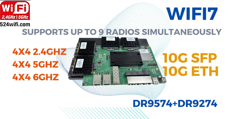
QCN9274 QCN6274 IPQ9574|What Does Wi-Fi 7 Actually Bring?
Amidst the flurry of technical discussions surrounding Wi-Fi 7, let’s bypass the intricate details and delve into its tangible benefits. Wi-Fi 7 represents a significant leap forward in data throughput and reliability, promising to transform the connectivity landscape for homes and offices alike.
At its core, Wi-Fi 7 aims to address the ever-growing demand for bandwidth in environments teeming with multiple devices vying for connectivity. By optimizing frequency space utilization, Wi-Fi 7 endeavors to minimize latency and maximize data transmission rates. The result? An enhanced user experience marked by smoother connectivity and fewer frustrations.
One of the standout features of Wi-Fi 7 is its remarkable speed capabilities. With a theoretical top speed of 46.4Gbps—four times faster than its predecessors—Wi-Fi 7 sets a new benchmark for wireless performance. Real-world tests have demonstrated Wi-Fi 7-capable devices achieving speeds around 5.8Gbps, a noteworthy 2.4 times faster than Wi-Fi 6/6E. Such impressive speeds open up possibilities for seamless streaming, faster downloads, and smoother online experiences.
In addition to speed, Wi-Fi 7 introduces Multi-Link Operation (MLO), a game-changer in frequency management. MLO enables devices to intelligently utilize the 2.4GHz, 5GHz, and 6GHz frequencies, seamlessly switching between them to avoid congestion and minimize interference. This dynamic frequency switching translates to lower latency, reduced packet loss, and heightened reliability—a boon for gamers, video streamers, and anyone reliant on a stable internet connection.
Consider the scenario of a Wi-Fi 7-equipped VR gamer immersed in an intense online battle. As interference threatens to disrupt the gaming experience, MLO swiftly kicks into action, seamlessly transitioning to a less congested frequency. The result? Lag-free gameplay and uninterrupted immersion, without the frustration of delayed responses or missed opportunities.
Moreover, Wi-Fi 7’s advanced frequency management holds immense promise for mission-critical applications like 4K/8K CCTV systems. Equipped with Wi-Fi 7, surveillance cameras can dynamically switch bands using MLO, ensuring uninterrupted footage capture even in the face of interference or network congestion. This means that crucial moments captured by high-resolution cameras remain intact, safeguarding security and enabling swift action when needed.
In essence, Wi-Fi 7 represents a paradigm shift in wireless connectivity, offering unparalleled speed, reliability, and efficiency. With its enhanced capacity, reduced latency, and refined spectrum management, Wi-Fi 7 is poised to redefine the way we connect and communicate, ushering in a new era of seamless digital experiences. So, whether you’re gaming, streaming, or safeguarding your property, Wi-Fi 7 ensures that connectivity remains steadfast and dependable—truly a game-changer in the world of wireless technology.
Retail Stores: 🛍️ In retail, a captive WiFi portal can be used to offer customers exclusive discounts or coupons when they connect to the network. It can also showcase new product releases, promotions, or loyalty programs to encourage engagement and drive sales.
Restaurants and Cafes: 🍽️ Restaurants and cafes can use captive WiFi portals to provide customers with access to menus, online ordering systems, or feedback forms. They can also promote special events, live entertainment, or happy hour deals to enhance the dining experience.
Hotels and Resorts: 🏨 Hotels and resorts can use captive WiFi portals to welcome guests, provide information about onsite amenities and services, and offer concierge assistance. They can also collect guest feedback, promote spa treatments or restaurant reservations, and provide access to streaming services or virtual tours of the property.
Healthcare Facilities: 🏥 In healthcare settings, captive WiFi portals can be used to streamline patient registration, provide access to educational resources or appointment scheduling tools, and deliver important announcements or updates from medical staff. They can also offer entertainment options in waiting areas or facilitate telemedicine appointments for remote consultations.
Event Venues: 🎉 Event venues can use captive WiFi portals to provide attendees with event schedules, maps, and directions. They can also offer interactive features such as live polls, social media integration, or photo booths to enhance the overall event experience. Additionally, they can collect attendee feedback and facilitate networking opportunities among participants.
Educational Institutions: 🎓 Schools, colleges, and universities can use captive WiFi portals to provide students with access to course materials, online resources, and academic support services. They can also communicate campus announcements, event calendars, and emergency alerts to students, faculty, and staff members.
Transportation Hubs: 🚆 Airports, train stations, and bus terminals can use captive WiFi portals to provide travelers with real-time flight or transit information, boarding passes, and transportation options. They can also offer entertainment options, shopping deals, and dining recommendations to enhance the travel experience.
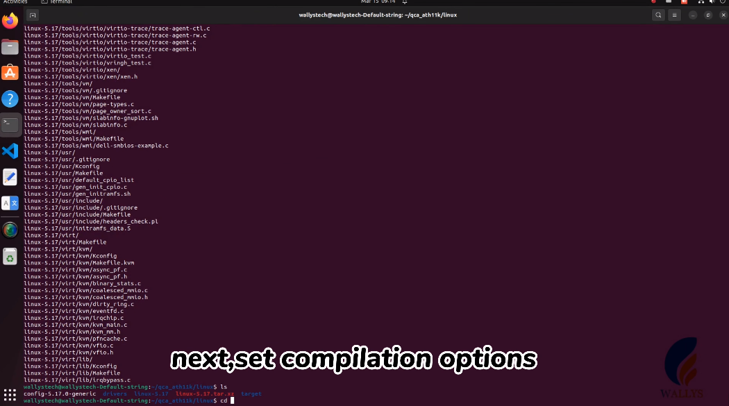
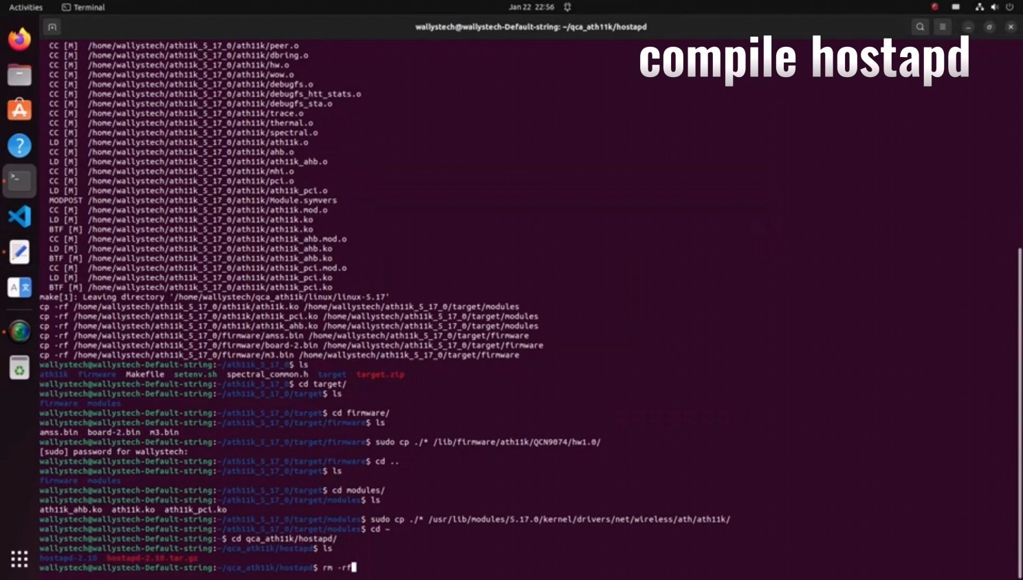
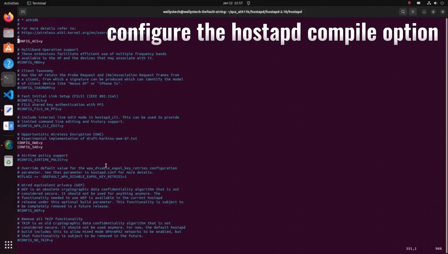
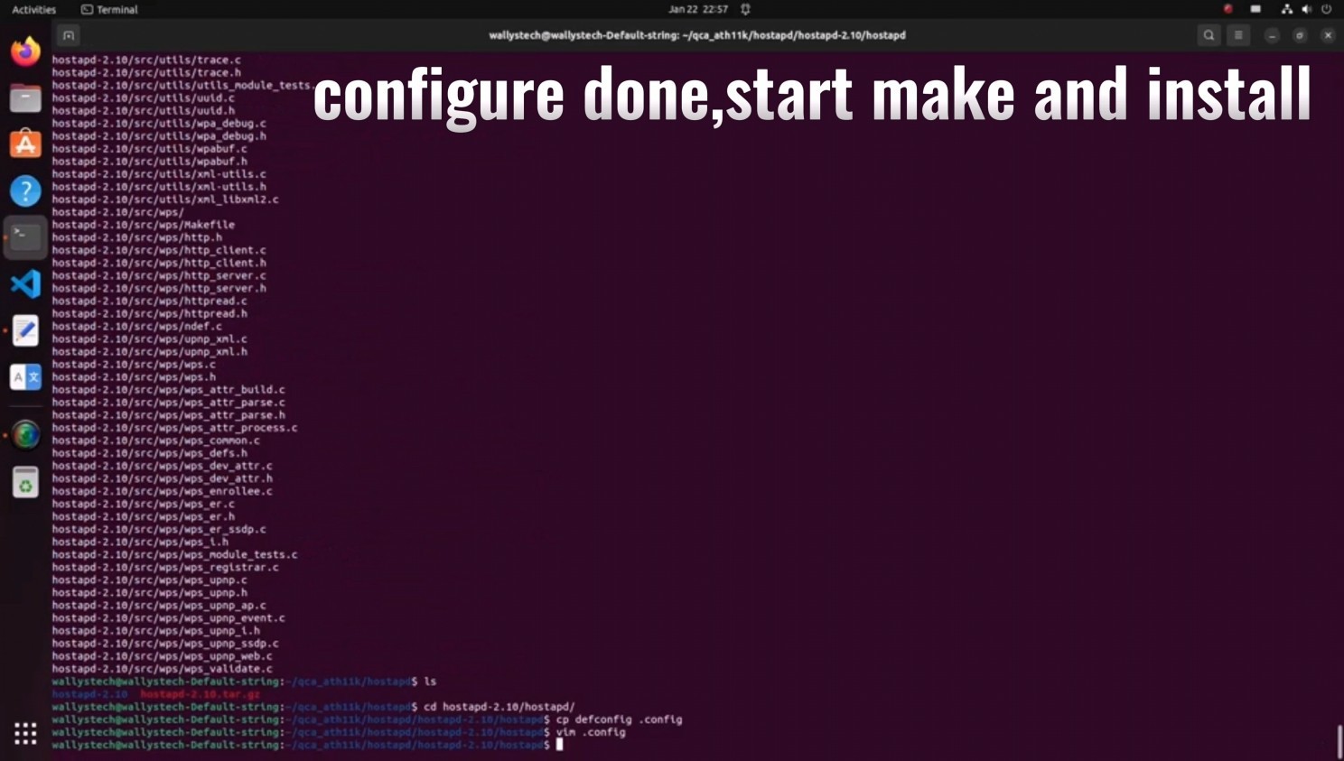
Check out our latest tutorial following the release of our video guide “How to Load Driver for DR9074-Triband on Linux.” We’ve received valuable feedback and have compiled common queries to bring you an enhanced tutorial experience.
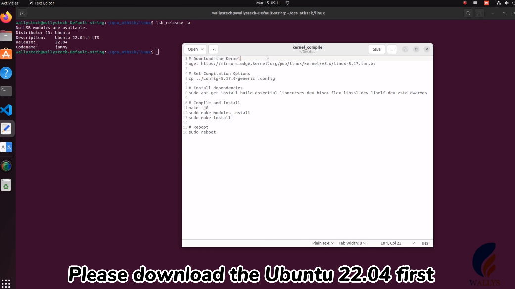
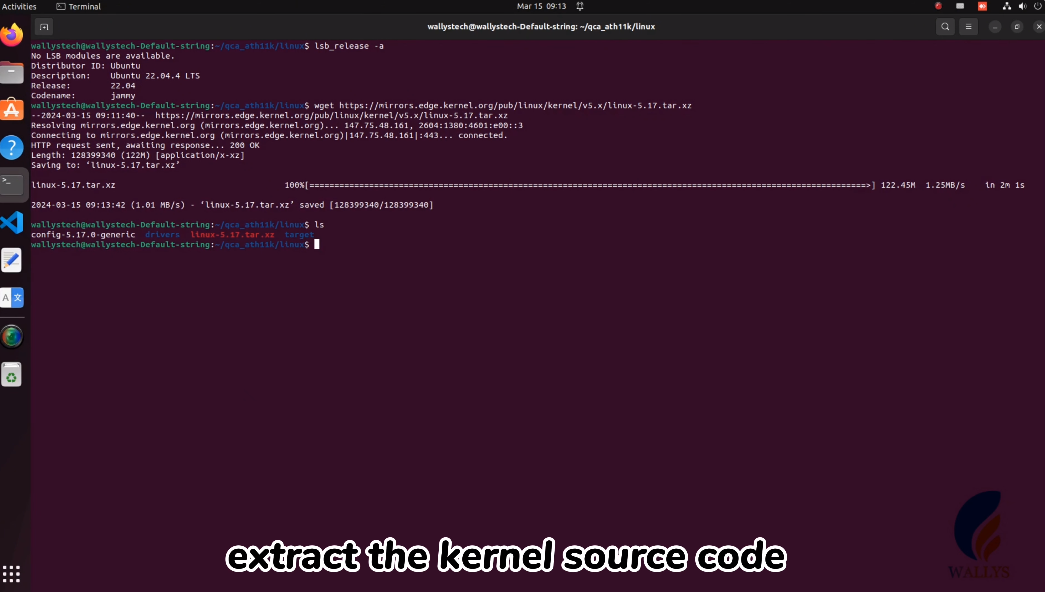
In this updated tutorial, we’ve included step-by-step instructions on downloading Ubuntu 22.04 and compiling Kernel 5.17, building upon the previous content. This video serves as a standard example, but you can customize it according to your specific project requirements.
Stay ahead of the curve and optimize your Linux setup with our comprehensive guide.
Imagine a scenario where an industrial-grade WiFi access point (AP) equipped with the capability to operate nine physical radios simultaneously is deployed across logistics, warehousing, ports, industries, and smart cities. Here’s what could happen:
1. Logistics Centers: In logistics centers, these APs could enable real-time tracking and management of goods. Each physical radio could connect to different sensors and devices, monitoring the location, temperature, humidity, and other information of goods. This data could be transmitted to a central control center over the network, enabling precise monitoring and management of logistics operations.
2. Warehousing Facilities: In warehousing facilities, these APs could optimize inventory management and goods allocation. Each physical radio could connect to different shelves or storage areas, synchronizing inventory information in real-time with warehouse management systems, improving inventory turnover rates, and operational efficiency.
3. Ports and Logistics Parks: In ports and logistics parks, these APs could facilitate real-time monitoring and dispatching of ships, containers, and transportation vehicles. Each physical radio could connect to different devices such as security cameras, sensors, and onboard equipment, transmitting data to a monitoring center over the network, ensuring the safe transport and efficient handling of goods.
4. Industrial Production: In industrial production, these APs could optimize the operation of production lines and equipment monitoring. Each physical radio could connect to different production equipment and sensors, transmitting equipment status and production data in real-time to production management systems, enabling automation and intelligence in the production process.
5. Smart Cities: In smart cities, these APs could enable intelligent management of city infrastructure and public services. Each physical radio could connect to different city facilities and sensors, monitoring information such as traffic flow, environmental pollution, energy consumption, and transmitting data to city operation centers over the network, enabling efficient utilization of city resources and sustainable development of the environment.
In summary, deploying an industrial-grade WiFi access point with nine physical radios across logistics, warehousing, ports, industries, and smart cities could lead to more efficient operations, smarter manufacturing, and intelligent city management.
In industrial Application
Configuring all nine radios as access points (APs) can bring several benefits:
1. Increased Device Connectivity: Industrial environments often require connectivity for numerous devices such as machinery, sensors, monitoring equipment, and mobile terminals. By utilizing nine APs, the network can accommodate a larger number of devices simultaneously, facilitating seamless communication and data exchange across various equipment and systems.
2. Enhanced Coverage and Reliability: Industrial facilities often have complex layouts and challenging environments, such as large warehouses, manufacturing floors, or outdoor areas. With multiple APs strategically deployed, the network coverage is extended, ensuring that devices throughout the facility can maintain a reliable connection with minimal dead zones or signal interference.
3. Load Balancing and Traffic Management: Distributing client connections across multiple APs allows for efficient load balancing and traffic management. This helps prevent network congestion and ensures that critical applications or devices receive sufficient bandwidth and priority access to resources, optimizing overall network performance.
4. Redundancy and Fault Tolerance: In industrial applications where uninterrupted operation is crucial, having redundant APs can provide fault tolerance and resilience against network failures. If one AP experiences issues or downtime, nearby devices can seamlessly connect to alternate APs, minimizing disruptions to critical operations.
5. Support for Mobile and IoT Devices: Many industrial processes rely on mobile terminals or IoT devices for data collection, monitoring, and control. With nine APs, the network can accommodate the growing number of wireless devices used in industrial automation, asset tracking, inventory management, and predictive maintenance applications.
Overall, configuring nine radios as APs in industrial environments enhances connectivity, coverage, reliability, and scalability, supporting the demanding requirements of modern industrial operations.
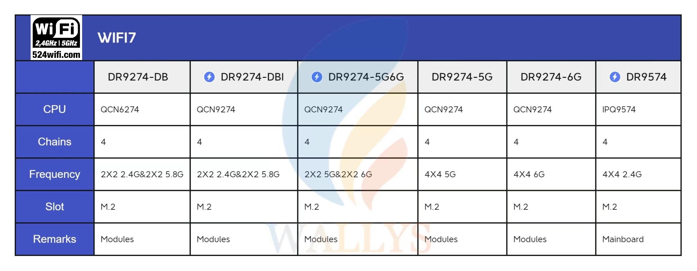
A Quick Overview for 524WiFi Dream WiFi7 modules
1. DR9274-QCN9274|QCN6274 WiFi7 Single Band 5G
2. DR9274-QCN9274|QCN6274 WiFi7 Single Band 6G
3. DR9274-QCN9274|QCN6274 WiFi7 Dual Band Dual Concurrent-2.4G&5G
4. DR9274-QCN9274|QCN6274 WiFi7 Dual Band Dual Concurrent-5G&6G
This tutorial builds upon the previous one and provides additional information on:
1.How to download Ubuntu 22.04.
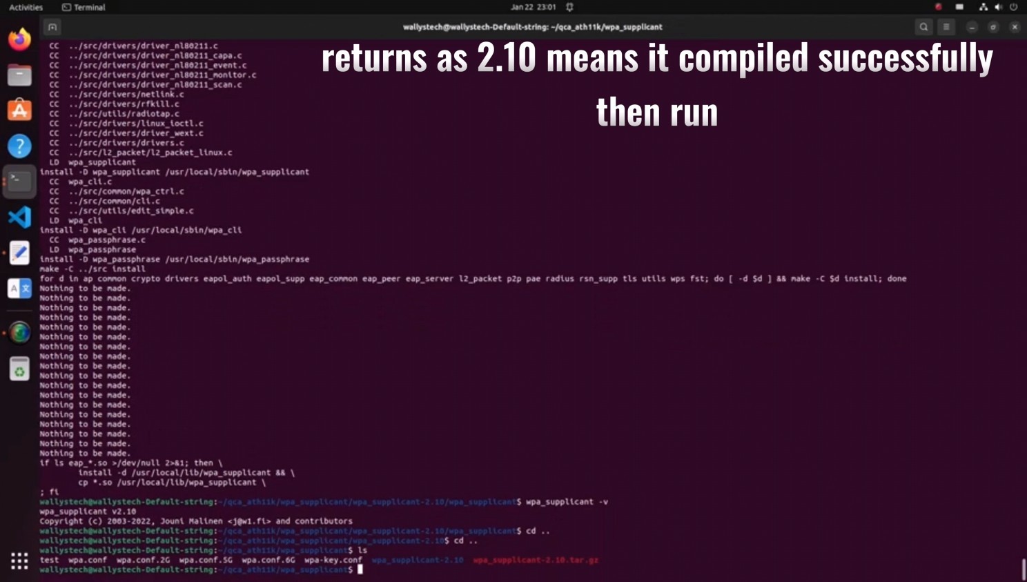
2.How to compile the 5.17 kernel to support ath11k.
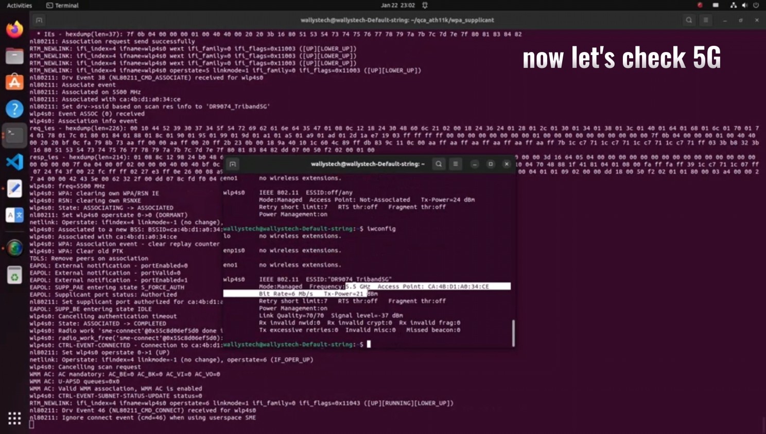
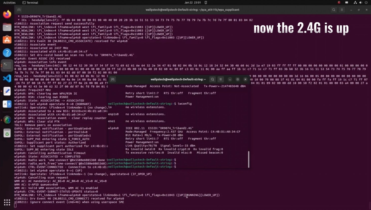
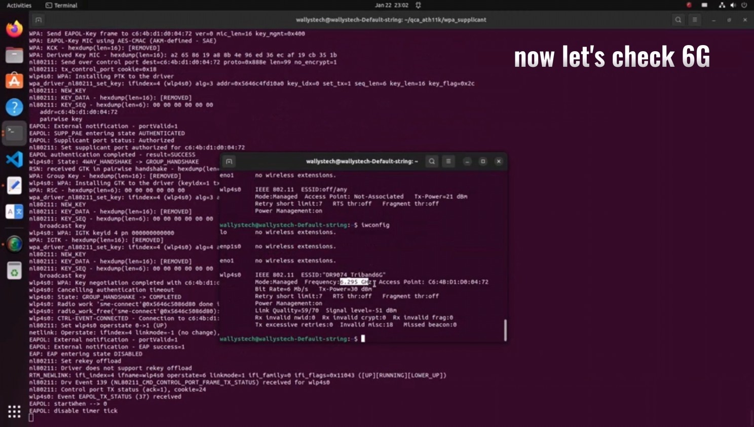
524WiFi recently announced the compatibility of DRiver m. module DR9074-TRIBAND with ATH11K on Linux, expanding its support beyond Qualcomm platforms to various Linux embedded systems, including Ubuntu. In this guide, we’ll walk you through the process of loading the driver for DR9074-Triband on Linux 5.17.0, demonstrating its seamless integration with ath11k. The module is showcased to function effectively in both AP (Access Point) and STA (Station) modes across the 2.4GHz, 5GHz, and 6GHz bands.
Introduction to DR9074 (QCN9024):
DR9074-Triband, equipped with the Qualcomm Atheros QCN9024 chipset, is an advanced enterprise wireless module. It incorporates a 4×4 MU-MIMO Dual Band Wireless Module, tailored for mobile access in high-bandwidth applications such as video streaming, voice communication, and data transmission. Key features include a maximum power of 23 dBm per chain, supporting data rates up to 4949Mbps. Operating in Tri-Band (2.4GHz, 5GHz, and 6GHz) with 4×4 WiFi 6E (802.11ax) and 4 spatial streams, it features an M.2 E Key Interface and PCI Express 3.0 Interface. Applications span security surveillance, commercial radio coverage, hotel wireless setups, and specialized scenarios.
Device Specifications:
Chipset: Qualcomm Atheros QCN9024
WLAN Host Interface: PCI Express 3.0
Frequency Range: 2.412GHz-2.472GHz & 5.18GHz-5.825GHz & 5.925GHz-7.125GHz
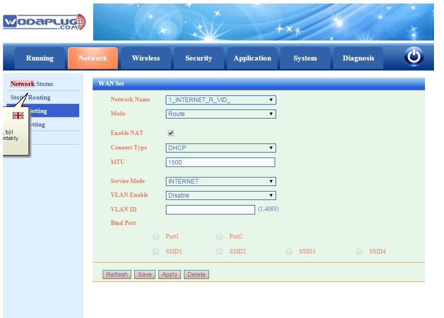
Attention – default config setup for newer EOC1121R4WL-R is with enabled VLANs for WAN configuration, so you need to check and set WAN configuration first and disbale VLANs if you not use them. Then i can work as before.
DEFAULT IP FOR MANAGEMENT : HTTP://192.168.1.1
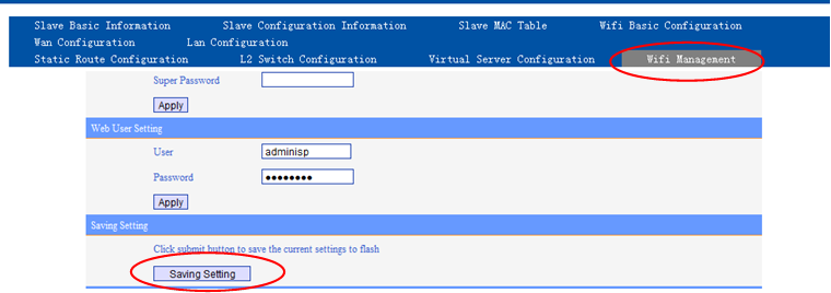
For the software, there is no difference between the old and new slave. Upon different usage, the new version have two login information. You can use admin and user acount. The admin name and password both are „admin“, while older EOC1121R4WL used super admin, the user name is adminisp, pwd: adminisp , this super admin login is used in latest SW versions for EOC1121R4WL.
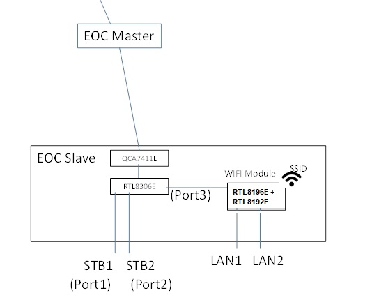
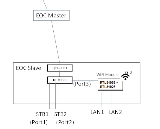
Newer HW version EOC1121R4WL-R use admin/admin for default super user access and user/user login for end user login to manage wifi and LAN only. The new version wifi slave is more flexible in the application than before. On the hardware revision, we add the 8306E switch chipset in the modem. It can controls the STB1 and STB2 ports which used as the Ethernet ports to setting the VLAN, rate-limiting, configuration,etc.
The LAN1 and LAN2 have the router feature which support the PPPoE. Moreover,the two mode can work at the same time.
QUESTIONS:
1. what is template 301 (and 302), I can’t find it in the list of template and modify it?
Template function is for user configure the slave convenient. There are a default template named “1”, is for the all slave as a default configuration. You can modify the template 1 in the SlaveàTemplate.
As you enter a slave configuration windows (it use the template 1), when you changed the configuration, the system will save a private template for this slave. The private template number will be 300+Slave ID. The private template is used only for this slave.
2. how many admins can be loged in? Where can I find loged in users?
No limit now. No record for it.
3. if I understad right, WAN means interface to WIFI module (oposite to port3) not the RF interface? Due to this STB1 (port1) and STB2 (port2) interfaces are always in bridge mode with or without VLAN?
Yes. WAN is connect to the port3.
STB1(Port1) and STB2(port2) is always in bridge mode.
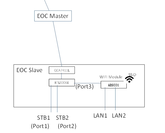
Differences : new version : RTL8196E(Routing Master Chip)+ RTL8192E(Wireless Transmitter Chip) replaced AR9331 (Routing chip integrated wireless transmission) in older version
3 – 3 .The way to change STB port as LAN port
Here is the way how to change this default configuration, if you need 4 LAN ports , then please proceed these steps:
Telnet to the slave unit (to its IP), Account: root/root626
command:
nvram_set stb_port 1 //1 means 2lan, 0 means 4 lan
reboot
The command to change status:
ralink_init show 2860 |grep stb
ralink_init show 2860 |grep wan
4. If i’am right in 3, why in WAN configuration of a slave over master web there are 4 LAN ports? In WAN setting from direct Slave web are only ports PORT1 and PORT2 that means LAN1 and LAN2 I think.
Because the WIFI module support 4 port max. In this slave, it have 2 ports LAN1 and LAN2. In other type , it have 4 ports. The WIFI management window display LAN1, LAN2, LAN3, LAN4 is compatible the 4Port product.
We will distinguish between different product in later version.
5. What does it mean PIB and NVM? –
NVM is the software for EOC 74 chipset (used low level Homeplug communication) .
PIB is configuration file of this chipset.
6. Where is connected router inside the box?
Please see figure in 3.
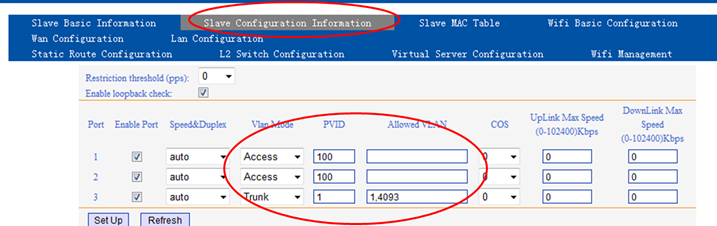
7. Where are VLANs processed?
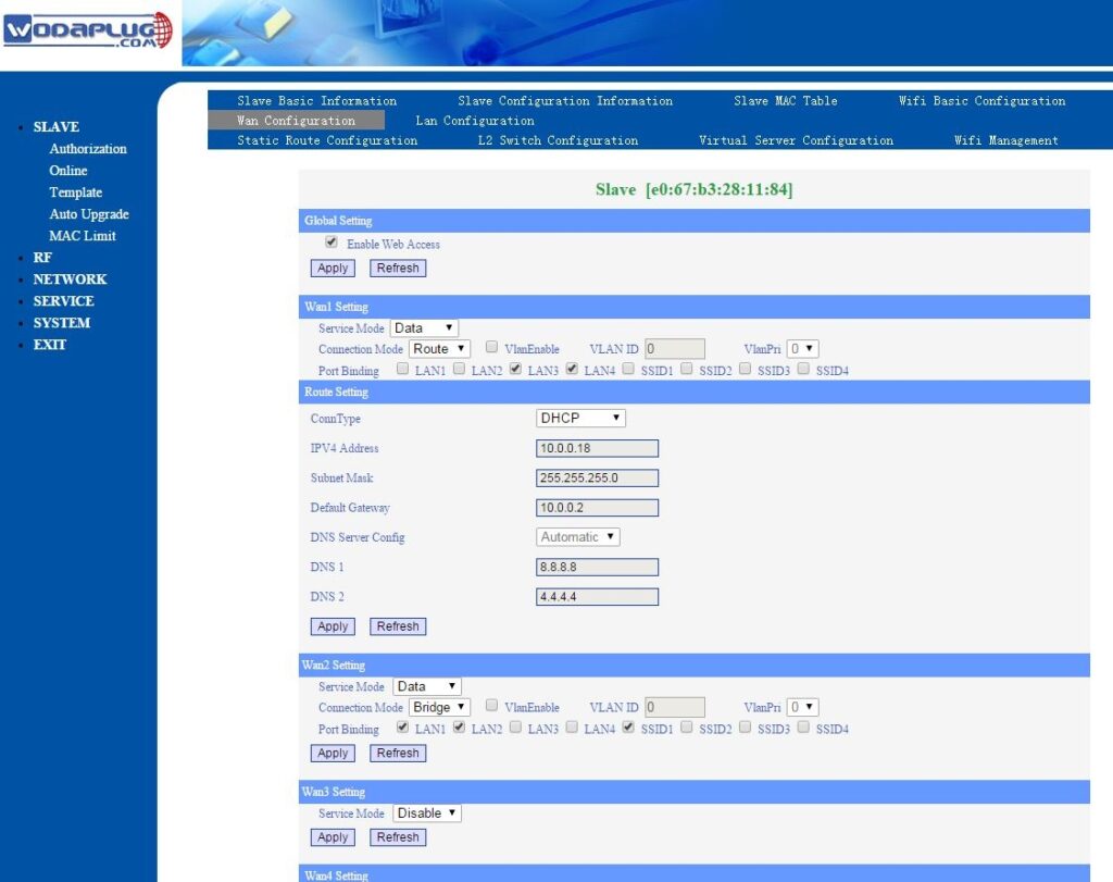
Slave – Online – Click the MAC you want to configure , enter the window as below.
attention – Please not use VLANs 1,2,4092 and 4093 , this VLANs are used for internal communication between Master and Slave !! So please not use this VLANs for your network.
8. When I set management VLAN I can’t set dynamic IP resp. I can but without effect, eth0 has no IP. The DHCP server was configured properly, there was no DISCOVER for DHCP from master.
This version do not support the DHCP+VLAN function.
It only support DHCP (no VLAN) and Static IP (VLAN or not).
9. I can’t disable SNMP on master
Software design so. It do not support disable SNMP.
10. Enable web access in WAN Conf of a slave over master web always fails.
Master and WIFI used the VLAN 4093 for OAM. Please try add this VLAN.
We will try to optimize it to configure in default. Solved in latest firmware versions.
11. Change setting in WAN Conf of a slave over master web doesn’t work. I set mode to route and after Apply I see change it to bridge etc, etc, etc. I’m not able to set what i want.
You need saving configuration as below.
12. How to set WiFi to bridge mode and use higher DHCP server for WiFi clients ?
attention – firmware 2.02 for EOC1121R4WL-R unit had a bug in bridge mode configuration, WiFi can not work in bridge. Please use latest 2.06 firmware or newer.
There are two ways for wifi client to get the DHCP IP address:
1. Using PC to link STB port directly, it can get the IP address automatically.
2. Set WAN to bridge mode, need to bind corresponding LAN port, PC link the bound LAN port, it can get the IP automatically.
STPES :
1 – open EOC WiFi slave web management (using its IP address), open Network and then WAN config. You will see dfault WAN1 config
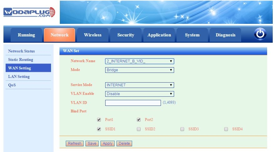
2 – Add new WAN2 and configure is as Bridge and Bind ports Port1 (LAN1), Port2 (LAN2) and requested SSID
3. – in lAN settings you can disable internal DHCP server.4. – in master WEB management you will see this WAN configuration of online EOC slave with WiFi :
Same setup for newer EOC1121R4WL-R unit : – attention, firmware 2.02 for EOC1121R4WL-R unit had a bug in bridge mode configuration, WiFi can not work in bridge. Please use latest 2.03 firmware or newer.Attention – default config setup for newer EOC1121R4WL-R is with enabled VLANs for WAN configuration, so you need to check and set WAN configuration first and disbale VLANs if you not use them.13 – How we can use 13 WiFi channels for Europe in EOC1121R4WL-R Slave unit? You can use US country to use 11 channels, or you can set Europe country domain using Telnet and CLI commands as shown bellow:telnet the onu IPlogin as root/root626flash set HW_WLAN0_REG_DOMAIN 1 //USAflash set HW_WLAN0_REG_DOMAIN 3 //Europereboot.
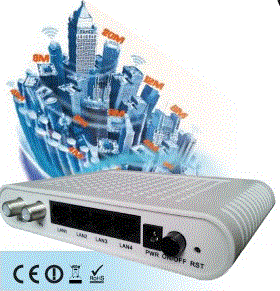
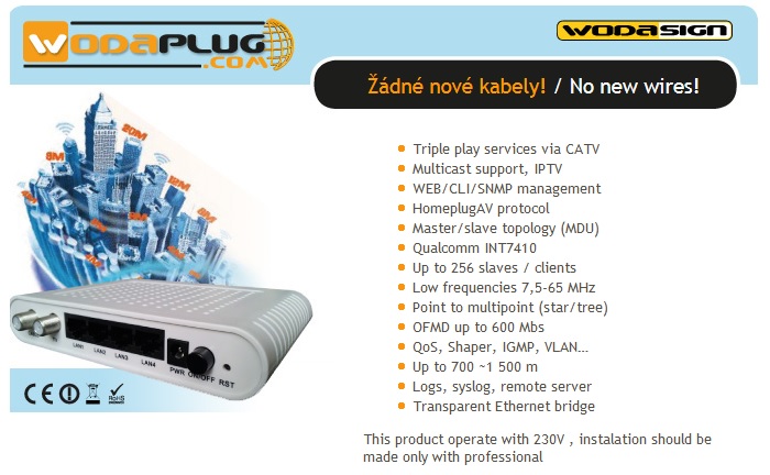
Wodaplug EOC products (EOC Master + EOC slave units) offer you the possibility to bring internet triple play services to every coaxial socket in the building, are suitable for coexistence with TV and satellite reception, it is possible to use the same cable and add a data signal to the input of the coaxial distribution to the existing TV/SAT signal. The installation is very simple, the only obstacle to the throughput of the data signal, which uses the band 7,5-65MHz (or 7,5-86MHZ version AV2) are active elements – amplifiers that are typically working in the band above 40MHz. Those amplifiers have to be bypassed by the bridge using Wodaplug diplexers. Wodaplug diplexers are used to separate the data and TV signals and then reunite them back. Real data throughput is 300-350Mbps (resp 500Mbps version AV2) and depends on line attenuation, until 20-40dB attenuation the speed is still close to the maximum, around 50dB attenuation the speed is still 100Mbps and the limit of functionality is attenuation above 65-70dB. Another limit is the length of the cable, the maximum direct distance between units is 1500m (cable RG59), in the rugged wiring above 700-800m the time synchronization of the used Homeplug technology AV can be thrown off. To achieve a longer distances it is therefore necessary to use an additional transmitting master unit for the next part of the line. Examples of real installations and typical connecting to coaxial wiring can be found in the section “how to install”.
Wodaplug EOC line behaves like a smart L2 switch in a transparent bridge, independent of protocols, operating systems, does not need any additional software. The central Master unit communicates by the wiring with Slave units, which are all configured from the web management of the Master unit. Slave units cannot communicate with each other. For slave units you can set automatic or manual authorization according to MAC, template for setting individual ethernet ports slave units and for all 4 ethernet ports Slave units you can configure different VLANs, QOS or Shaper. Typical deployment is for example 2 ports set as STB with VLAN for IPTV or VOIP and two ports with VLAN or without for Internet. Multicast support is also a matter of course, IGMP, storm and loop protection. There is also a Slave unit with WiFi, which can also function as a router with NAT or as a bridge.
Slave Units Management: (configuration template support!)
Setting the connection permissions according to their MAC address
Statistical information to each unit, attenuation, SNR, RX/TX
Broadcast protection statistics, adjustable for each slave individually
Setting VLAN 802.1Q parameters for each LAN port slave device
Upload/download band settings for each LAN port slave device, there’s also an option to set the aggregate transfer limit for the whole slave device
Priority 802.1p for each LAN port slave device
Remote upgrade slave units, remotly rebooting units
Possibility to use templates to set slave units
Master Units Management:
Web management, CLI – telnet+ssh, SNMP monitoring and surveillance, transmission statistics
Setting VLAN 802.1Q for management interface master
Settings protection against broadcast storm
Independent LAN port for local management
Upgrade from ftp, remote reboot, import/export configuration files
Logging, syslog to remote server
In practice, we recommend installing a maximum of 25-30 (or 40-50 for the AV2 version) slave units to one master unit in one coaxial distribution system; when planning, consider that the bandwidth of the coaxial wiring is common to the slave units and it is good not to exceed this number to maintain quality services for the users. From practical deployments it is verified that, for example, an EOC line in an apartment building can handle 10 SD or 5 HD different IPTV channels + guaranteed internet services at the same time, with multiple IPTV channels running at the same time the image can start to pixelize. The unit coexists with the TV signal and does not affect its reception (DVB-T/C/S).
If you have any questions about the use of Wodaplug EOC technology or the preparation of coaxial wiring, do not hesitate to write to info at wodaplug.com. Read more practical experiences and advice here, or contact us throught our website.
WodaPlug EOC Master supports up to 256 Slave units. Recommended is to install max 30 – 40 Slaves.
VLAN and QoS function 100% supported!! Each Slave port can run different config.
Meet the IEEE Home plug AV and IEEE 1901 standard
The lower design – Node device is the main equipment of access network equipment. Functional module with low power design not only reduces the operation cost but also beneficial to environmental protection, energy saving and emission reduction „response strategy for building “green” communication networks.
The indoor and outdoor type products adapt to different application scenarios.
Indoor type The EOC Master is usually placed in cabinet, corridor, basement or patio. Wodaplug’s indoor type EOC Master products are designed with metal shell and built-in power supply. They satisfy the corridor environment requirements. These items have anti-lightning, anti-dust and good heat dissipation characteristics.
Outdoor type The outdoor type EOC Master is designed with an aluminum shell. It has a good waterproof, dust-proof and heat dissipation effect. With the high reliability of the switching power supply and lightning protection design, it ensures the device can work stable in poor environments of the field.
The Qualcomm AR7410 chipset solution – AR7410 AR74 series of EOC products are based on HomePlug AV technology. It complies with IEEE 1901 standard and adopts Qualcomm AR7410 chip and OFDM Module technology of high interference resistance. It supports 4096QAM and takes up frequency between 7.5MHz-65MHz to transfer data. Its physical layer bandwidth is 600Mbps, while the maximum MAC layer bandwidth is 320Mbps.
The MSTAR 1000 chipset solution – Gigabit EOC AV2 1000 series of EOC products is based on HomePlug AV2 technology. It complies with IEEE 1901 standard and adopts MSTAR 1000 chip and OFDM Module technology of high interference resistance. It supports 4096QAM and takes up frequency between 7.5MHz-86MHz to transfer data. Its physical layer bandwidth is 1000Mbps, while the maximum MAC layer bandwidth is 500Mbps.
The data service function Support VLAN division and management. support IGMP. support the same equipment at office end user mutual isolation. Support a broadcast packet / unknown packet suppression. Support MAC addresses limit function, link aggregation function, port mirror feature, etc.
The performance of QoS Support the VLAN tag or IP QoS to automatically distinguish between different services based on the priority for ensuring the high priority. Each Slave port can run different configuration. It supports automatic configuration templates – provisioning.
The complete network management function Support multiple network management mode and protocols, such as WEB, SNMP, CLI, etc. Provide user-friendly CLI interface and graphical interface based on WEB for easier using. Independent researched and developed unified network management software based on B/S architecture can realize the management of the ONU, MC and EOC equipment. The users can carry on centralized management of equipment, complete the configuration parameters, monitor working status and diagnose faults to meet the demand of network operators and maintenance.
It is adapters for data transfer Ethernet over coaxial cables, based on technology HomePlugAV, which offers a large range (700-1500 m), high speed (physical speed to 700MB / s speed on the MAC layer 350MB / s), interference immunity and operation even under heavy sedation.
EOC slave unit is designed for end users and works with EOC master unit for connection and transmission of Ethernet over coaxial distribution. The mixed signal again converts to Ethernet data output signal and TV output TV. Newest versions of the chip QCA7411L is used.
EOC slave + WiFi unit is designed for end users that need WiFi router or bridge and works with EOC master unit for connection and transmission of Ethernet over coaxial distribution. The mixed signal again converts to Ethernet data output signal and TV output TV. Own IP address for management.
This new MSTAR 1000chip Homeplug AV2 based EOC masters can offer 500 Mbps real throughput over existing coax cable network for long range up to 1km. Can work with Wodaplug 1000 AV2 EOC slaves. Work frequency range is 7.5Mhz-86Mhz / AV2 and Physical DataRate is 1000Mbps.
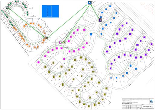
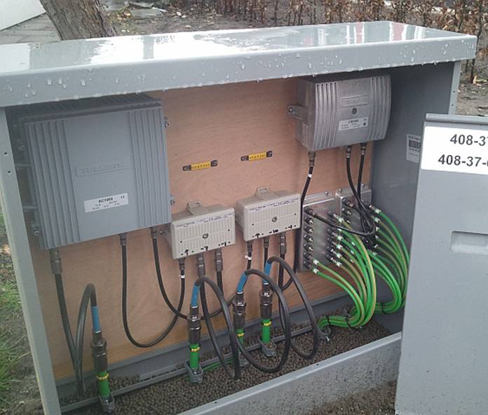
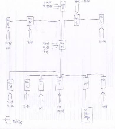
Here we will discuss in detail one of our larger installations in the holiday resort of Landal Resort Haamstede in the Netherlands. This resort has a large area and has a total of 150 villas which have been introduced into the central STA distribution and customer requirement was to equip each villa toll connecting to the Internet. Thanks to the vastness and complexity of the sector was not possible nor appropriate use of WiFi coverage, after studying design documentation and test throughput cable networks, we have opted for HomePlug adapters. In collaboration with a network technician of a satelite distributions we made modifications to existing distribution systems to ensure throughput.
Illustrative pictures before and after installation:
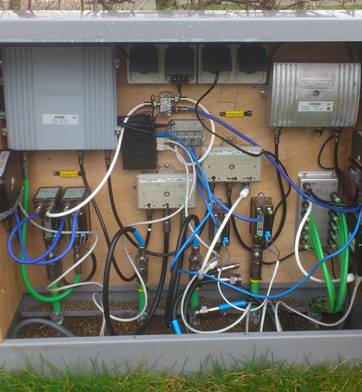
1 – one of the cabins with the hub before installation
2 – Simplified diagram of coaxial network
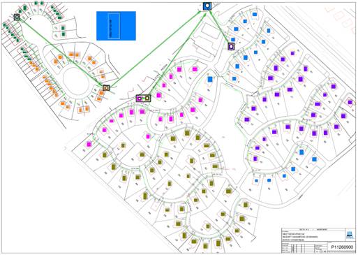
3 – Project of the Ministry of marking STA distributions – starfish, color-coded according villas MASTER units
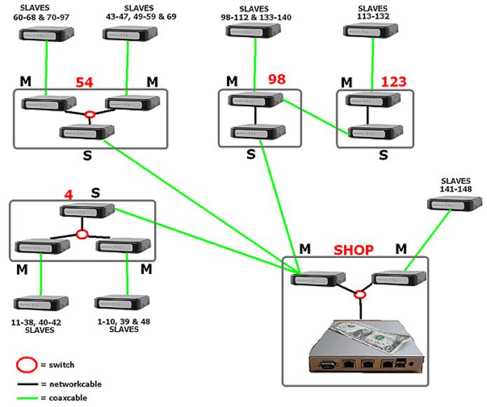
4 – Diagram of the network after installing the Wodaplug adapters 200C / N
To guarantee the quality of the network – a quick response, we adhere to a maximum of 20 slaves to one master unit and max 4 MASTER units on one shared cable. Network is why we have divided into two stages – MASTER level1 – Slaves level1-Masters l.2 l.2-Slaves We used to level2 HomePlug units 200C / N 200Mbps and faster HomePlug level1 500C / N 500MB. For connecting the master and slave units into the existing distribution we used diplex filters.
When installing, we had to solve the problem of looping network. It was necessary to separate adapters level1 and leve2 to prevent accidental transmission, install adapters ie min 20 cm formed must be separated from each other and their power powerline filter or UPS. It was necessary to divide the network into subnets using different network passwords and settings Static eating breakfast (numbers 1 to 15) for all MASTER unit for optimal packet flow.
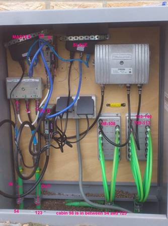
5 – Typical cab after installation – Slave receives a signal from Master l.1 l.2 it then sends forth to Slave l.2
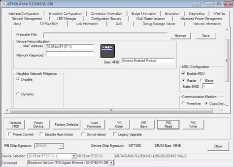
6 – Sample configuration adapter HomePlug MASTER
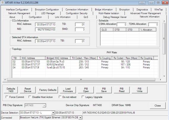
7 – Demonstration network statistics – the quality of the signal / baud rate for the network level1
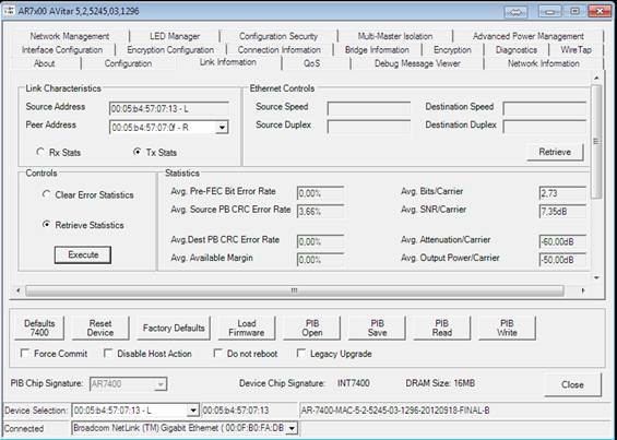
8 – Sample network statistics – signal, attenuation and error between master and slave level1
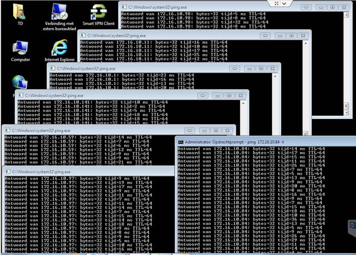
9 – Response – ping across the network during normal operation (ping from a central PC to the terminal units in villas)
10 – Demonstration network utilization – Internet resource is 12Mbps ADSL connection, for guarding and monitoring operations we have these larger installations developed a special piece of software called “watch dog”
This is realized in practice functional connection example
In most cases you can secure the network without unnecessary additional costs
In the case of this powerful area of the resort and taking into account the assignment or other solutions have been – here clearly see the use of technology compared to the possibilities of Wodaplug powerline standard enduser
Don’t know how to do it ??? Please contact us and we will help
PRACTICAL EXPERIENCES AND HOW TO USE WODAPLUG EOC MASTER AND SLAVE DEVICES IN COAXIAL TV OR SAT NETWORKS – SOLUTIONS FOR PROBLEMATIC SITUATIONS
COAX CABLE LINK ATTENUATION
When you use the EOC Wodaplug Master and Slave units, it is necessary to have coaxial lines in good conditions. For TV signal transmitted in band above the 85MHz may be all well and good, but it doesn’t have to be same for range 2-65MHz.
On the route to the Slave there is always some attenuation on the main coaxial cable, but also passive elements such as hubs, splitters, connectors. The hubs is nessesary to calculate with the weakening in 3.5-4dB for 2-way splitter, 3-directional attenuation has a 5.5-series 6 d, 4 directional around 8dB, 6-directional approx. 12dB. turners have an intermediate direction of attenuation, attenuation is by the type of splitter around 1dB.
I tis nessesary to realize, that this kind of attenuation is between input and output. Lets pretend – If we would connect master unit likewise oposite direction, direction to input there will bet he same attenuation , but towards another output this very same attenuation will be much higher, during the manufacturer datas, it will be around 25-30 dB. It means, that if we would like to inject master unit somewhere located in middle of network architecture and not on its begining (ofcoarse not over build in diplex module, but over whole splitter) , there will be in one direction attenuation for example thru double splitter apr 4dB, but for passing part of the network it will get as much as around 30 dB.
Becoase of that, if we want to use master unit to higher distance, where every degree of attenuation counts, is very very important to find perfect spot for master unit placement injectment, ussually best possible is near or next to group station, optical reciever (see our other optical products or our already connected willage sample), or simply source of the signal.
The difference in temperature, also causes differend attenuation shown by master unit in the summer and another in the winter. For this you need to remember, especially if it is some sort of Slave to the edge of the parameters in the winter, it can be assumed the problem with arise in warmer weather, therefore,to avoid this as much as possible, enhance the route parameters.
The values indicated in the management of wodaplug master through a Web interface are very helpful, although they are not completely accurate, they help create a picture of the quality of the network and its individual segments.
CONNECTORS – RUST IS BLAST
A very important part of the koaxial network are connectors, or the execution of their Assembly. By The influence of time and meteorological conditions, however, the metal parts of the oxidation layer is generated, which increases the resistance of the structure. What has a very negative impact on the transmission, mainly in TV zone, in which bandwith these devices works as well. From ours many years of experiences, we can state that the situation can be drasticly improved by cleaning every connection, IE. screw out connectors, spray over with a suitable spray eg. Contact 60 and screw back the connector. The parameters of the connection between wodaplug Slave will improve. doing so on whole route between wodaplug master and slaves, it will make a significant improvement in SNR, which ultimately will increase parameters of the network throughput. When outdoor hubs/splitter are well maintained too, it will also help. Always keep in mind !!! Rust is blast for your network.
We had a lot of cases where the wodaplug Master unit showed attenuation around 60dB, and even sometimes wodaplug slave unit was not available, After treatment of the route the parameters of the connection improved so greatly, that downturn was suddenly only 50dB and the Slave unit goes steadily ever after. (it really happend many times in our instalations and not only at kingdoms far far away )
Sometimes when experiencing bad parameters of the network – may help to reduce the output power of master unit, whether using lovering cells or through the Web interface. Sometimes in network may be a weaker place, for example poorly made grounding, network cable (dismantled or badly fitted drawer). This place then causes a strong signal reflections, and then distort the signal and so worsen the parameters across the whole network, which has an impact on the availability and the slave units to communicate.
GALVANIC SEPARATORS
Another of the problems that may emerge, is the formation of various currents flowing thanks to connecting multiple several different groundings, for example. from the various phases of a variety of grounding terminals, grounding … Each grounding unit has a different potential and when they come across such a pack of two, there is rising of the potential for tension between them and current begins to flow between them. It is, however, interference for TV signals within 65MHz and reduce it again the total capacity of the transmission, or it may cause disconnection of slave units from the MASTER unit.
Also the source of such interference can be made by a source of tension, for sample bad adapter, the TV networks are often involved in computers networks today, for example: TV with 3way plug, in this way, there is unwanted conection between grounding from TV network and it colides with grounding from EOC network and we have problem alive. Such interference can often be seen in the main TV picture of the analog signals such as moving vertical strips.
The solution may be galvanic separator, that separates these different groundings or resources. The best prevention is to involve galvanic separator at the start of the tv antenna network (at the entrance to housings), this way you split/separate networks from each housing/area etc., if that doesn’t work, then you have to find the line bringing interference to TV networks and install (after punishing owner of the housing) galvanic separator for this connection. proven by years of experience you may find this type of Polytronu model KTG220F very usefull. if you need to buy this or any work proven type, let us know.
DIPLEX FILTERS
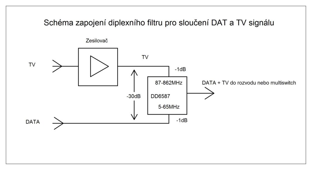
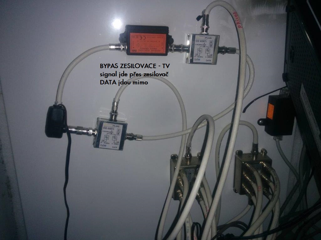
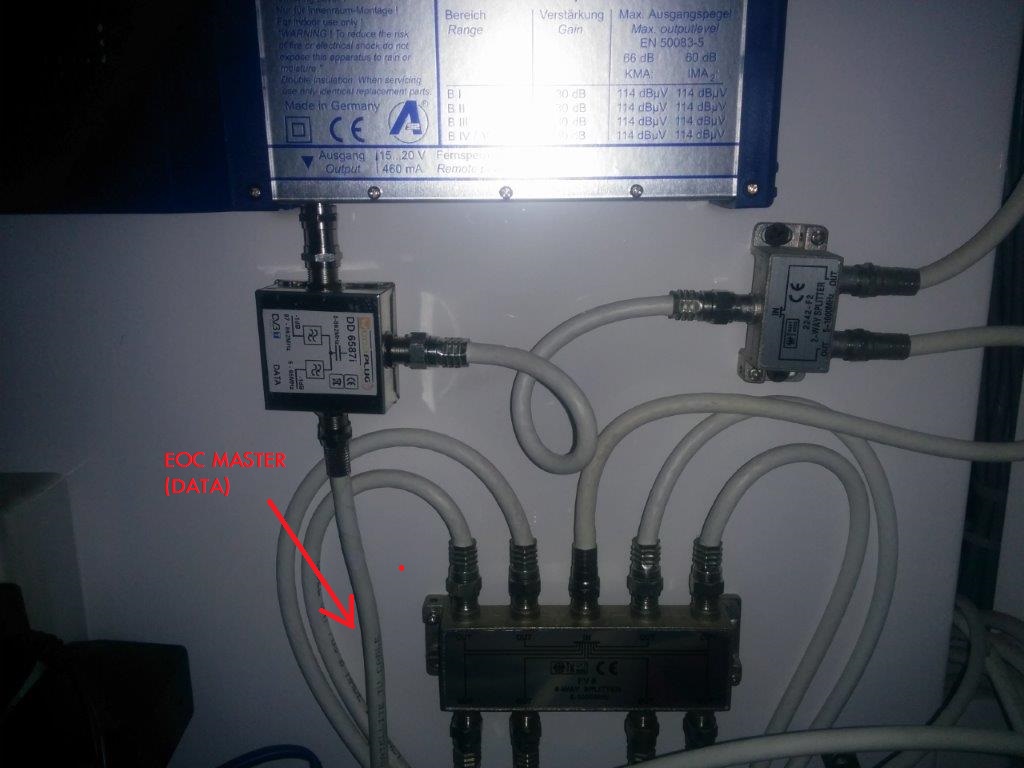
Whereas these data signals spread in TV networks in the 0-65MHz back and forth directions, is necessary to ensure this way goes mainly through the amplifiers. Some of them (especially older nets) have only the active a reverse way, However, it is possible to bypass those amlifiers with pair of diplex amplifiers filters. The input signal to the amplifier plugs into the filter input 0-860MHz diplex, output of diplex 85-860MHz will be connect to input of amlifier, on the other side of this amlifier you connect signal again to diplex 85-860MHz and output from diplex 0-860MHz continue to tv network. In addition, these two diplexes are connected thru inputs 0-65MHz, which in real does so called bypass of the wired signals twoways around that amplifier.
The second option is to Replace amplifier with new with passive back direction 0-65MHz, what may also be a partial improvement of the signal due to the involvement of other connectors and jumpers in bypass.
COAX NETWORKS WITH MULTISWITCH
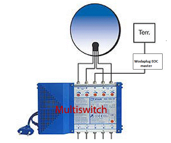
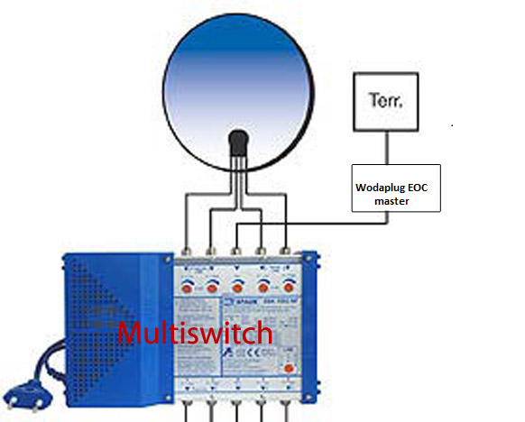
Another option for connecting wodaplug is thru multiswitch – you need to connect Wodaplug eoc master to original terrestrial multiswitch antenna input and multiswitch has to be in passive mode (make sure device is set in passive mode, ussualy its possible only when amplifier is off !!!) – thats what we dont want so often so we come to other possibility.
Amplifying terrestrial signal with wodaplug in network thanks to its build is still possible, but used amplifier has to be connected between Terr. antenna and wodaplug EOC master device to not block data signal injected by Wodaplug EOC master in to Multiswitch. As every plus has its downside, we strongly recommend to lower output power on EOC master unit, in web interface on RF parameters section or using the cell. Try to find best solution to avoid interferences. By our experiences is to lower signal to 112 – 110 dB for medium or bigger networks and 90-92 in smaller networks. At the place of wodaplug slave installation (end customer place – network user) , use ordinary diplex filter, avoid using wodaplug slave as direct coming thru signal in this scenario. You must separate bandwitch with diplex unit up to 67 MHz for slave unit. Please, bear in mind to use some good quality products.
there is even third, ussually best option:
Wodaplug lab offers to ISPs option to bridge your old multiswitch units to make it EOC friendly by inside installing data/bandwith bypassers, we need to know what type it is and other helpfull info before we start . The price starts around 99 Euro per unit and may vary from case to case.
PRACTICAL EXPERIENCE
In practice, there been implemented a number of contracts with these devices on different types of networks and cables. Maximum achieved a distance of up to around 1800m, with the assistance of the use of the transponder/repeater in around the middle of this route, while the main route was on the cable type 860 (these are the ones used on major routes cables -most fat ones :)- ). When you plug in the transponder/repeater means slave and Master, it is necessary to separate the zone 0-65MHz for for those two units, whether by the filter, as well as it is best to engage the input and output of the amplifier, which has turned off reverse way 0-65MHz.
Whereas, however, the larger the trail, the more connections and devices connected to the network, and thus even more sources of interferences by the various reasons described above. Therefore, it is advantageous, as it can be, to make a passage through the optical network (please referr to our optical networks part) and up to its end of the optical node and put the Master connected to the media convertor(please referr to our optical networks part). there are many of networks made this way, and the descibed problems disappeared,with no record of another problems. we split the network to half by this fibre-optic network and thus we achieved a significant reduction in interference in a separate network. wodaplug optic network are very reliable with best possible price.
As regards the number of wodaplug slaves on one wodaplug master unit, We have a networks, where it’s around 30 slave units, some customers have around 60-100. There should be no problem to involve even more of them, including around 120 as indicated by the manufacturer. Much more important is to do so called speed shaping through an external router/server, best suited by brands us Mikrotik , etc. These routers allow you to specify where the speed for each user sets with higher logic with respect to input connectivity. Although the master allows you to set the speed for each of the ports the slave units, however, redistribution is not used as a parameter value of input connectivity and, therefore, the greater the use of capacity to the network may seems sometimes in bigger networks cause stocking the network. The involvement of external router/server, which is managing , the problem disappeared. Of course, if 100% connectivity is used, the only solution is to increase the input connectivity.
A very important parameter, as I have already mentioned, it is, Its SNR It is, therefore, the signal-noise separation which determines the quality of the network for a given point of the network.
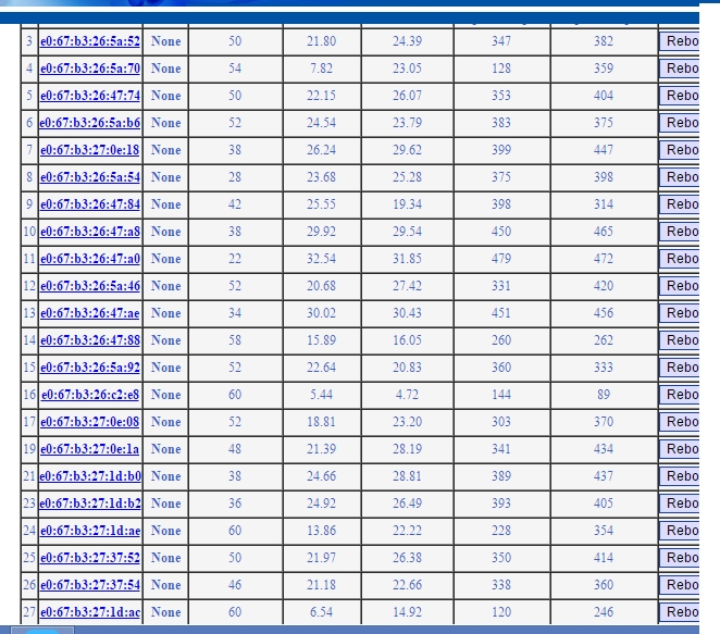
This is a list of wodaplug slaves of the one master, where the connection between the SRN and the attenuation can be seen, in this network we have sometimes blackout only with the slave with the attenuation 60dB and SNR 5,44 and 4.72, but we talking the line in the House, where it goes through the hubs, couplings, connectors, link x it would be quite ok, if better conection can be possible. On the other hand, the slave, the fourth farest from the end has same attenuation 60dB, but the SRN 13,86, and also 22,22, whereas it is involved through less splitters, hubs, connectors, and so it also has a much better parameters speed. It is the most reliable attenuation around up to 50dB, but it works very reliably even at higher attenuation.
Real speed on this network was 100 MB/s, which is in many cases exactly the connectivity, but we have information from one of our customer that it had tested well at much higher speeds in real. It’s mostly about the technical parameters of the network, the device can really achieve the speed specified by the manufacturer is used chipset. Then when we reach over 300 MB/s speed tests.
The reference projects – Ethernet computer network over existing coaxial cable distribution (SAT/TV)
APPARTMENT – INTERNET AND HD IPTV FOR RESIDENTS– WODAPLUG EOC MASTER + SLAVE
Multi-floor apartment house, guest house or hotel with an existing coaxial network needs simply and without additional cables distribute the internet and IPTV to individual apartments – rooms. Thanks to the several floors and the area which makes it dificult to cover it by WiFi signal, to install the HW and also the amount of WiFi accesspoints would significantly burden on the electricity bill. Putting the new cables is not always possible. Therefore, let’s use the coaxial network which is nearly always present either as a common TV antenna (tree) or as a satelite network incoming signal with a hub (star).
Example of use in practice :
Wodaplug EOC Reference – deployment in apartment buildings connected by the optic cable on the internet network and the IPTV for individual entrances through the existing coaxial wiring:
In apartments there are an existing coaxial network systems, whether satellite antennas with combiners or splitters or the common television antennas. Tv technician simply adjusts the active parts in the network for every entrance of the house so it is bi-directionally data-through for band 6-65MHz and after that we connect Wodaplug EOC master to the input combiners / the splitters and then install end units Wodaplug EOC Slave to the individual flats. For each entrance of a residential house is typically one Master to one common coaxial network. The Master unit has the IP address management to setting up the service / VLAN and QOS for individual clients. EOC line acts as a transparent smart Layer2 switch.
Therefore, in the apartment building, which is connected by the fibre optic, We connected master unit via Gbit dac. Further, there has been connected a total of 5 client units in the apartments of the final customers. Into the apartment on the specified VLAN runs IPTV in the form of a multicast. It is tested that the master unit can handle the 4 clients to deliver data for 4 different HD programs in a multicast. The fifth channel on the fifth unit was only SD, therefore a total flow was about 200Mb/s. Every HD program that we ran was moving data around 40-50Mbit/s. at least this flow flowed on one Vlan. At the same time with this multicast TV service still ran internet speed 100Mbit down. For each customer reserved 20Mb on the internet. Therefore, a total of approximately -300Mbit of service. At this load, everything worked and the picture on any channel has’nt made any mistake. But if we’re already turned on a HD program on the fifth slave unit (the other 5-th HD program), It has variously started to err IPTV picture and at different times on a different slave units it began pixeling or scramble. We reached the limit capacity of the EOC line between 300-350Mb/s. Therefore, for using IPTV with HD channels it is applicable for 4 to max 5 Slave units 100Mbit flow reserved for internet. Then the band for the transfer of data is already almost fully taken, it is possible to reduce the reserved part for the internet if you need in one network/the entrance of the house more than 4 customers with the service HD IPTV.
So thats in a nutshell everything about the practical test and deployment with HD IPTV. If it‘s just on the internet, then it’s cool and works even with 20 users and we don’t even know about it.
Connection to the network with splitter and Amplifier – For example 2 apartment houses connected by coax
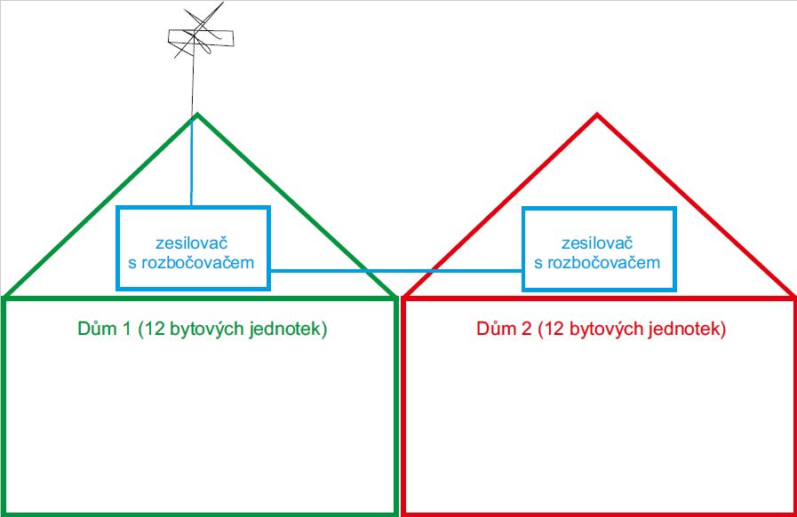
This is a practical realized example of Wodaplug EOC technologie connection into the existing SAT/TV splitter of 2 neighbor apartment – ilustration of the situation:
Detail of the previous existing splitter – in house n. 1 is merger with amplifier and with a splitter, in house n. 2 is amplifier and splitter. Then where should we place a data entrance and how we can solve a amplifier pass thru?
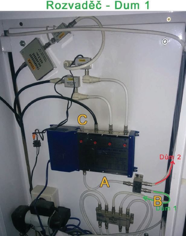
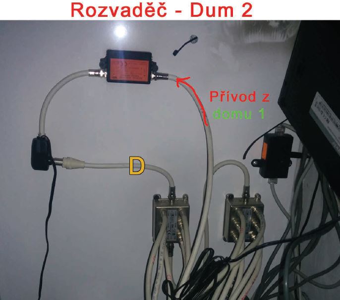
Solution: In a point A in house n.1 connect thru a diplex filtr Wodaplug EOC Master TV and DATA come into the splitter in the house 1 and at the same time into the house 2. At the entrance of the house 2 (in place of the red arrow) insert a diplex filter – input will merge the DATA with TV. Output of the TV plug into the existing amplifier. To the point D connect other diplex filter– TV input into the amplifier output. The merged output of TV and DATA plug into the splitter. All we have left are the two outputs of a DATA on these diplex filters – connect them with the cable and now it start working – so data will go outside of the amplifier – so called bypas.
result : TV and data running in both houses! Photo of complete functional connection