Wireless is usually the last spec finalized on an edge AI hardware design and the first thing that becomes a bottleneck in the field. Worth a closer technical look before your next carrier board revision locks in.
The RF problem, precisely
Dual-band designs (2.4GHz + 5GHz) share spectrum with every consumer device, AP, and IoT sensor in range. In dense deployments — multi-robot fleets, factory floors, warehouses — this shows up as elevated retransmission rates, unpredictable jitter, and tail latency spikes under contention. For a control loop or a real-time inference pipeline streaming sensor data upstream, tail latency is what actually breaks the system, not average throughput.
WiFi 7 (802.11be) addresses this at the PHY/MAC level in three ways relevant to edge AI hardware:
6GHz band access — largely unlicensed spectrum with far lower device density than 2.4/5GHz today, meaning lower channel contention and more predictable airtime
320MHz channel bandwidth (vs. 160MHz max on WiFi 6) — higher raw throughput ceiling per link
Multi-Link Operation (MLO) — the ability to aggregate or fail over across bands simultaneously, so a device isn’t fully dependent on the health of a single channel
For an edge AI box pushing multi-camera streams, sensor fusion data, and periodic model/OTA updates concurrently, MLO plus 6GHz access is the difference between throughput that holds up under real RF load and throughput that only looks good on an open-air bench test.
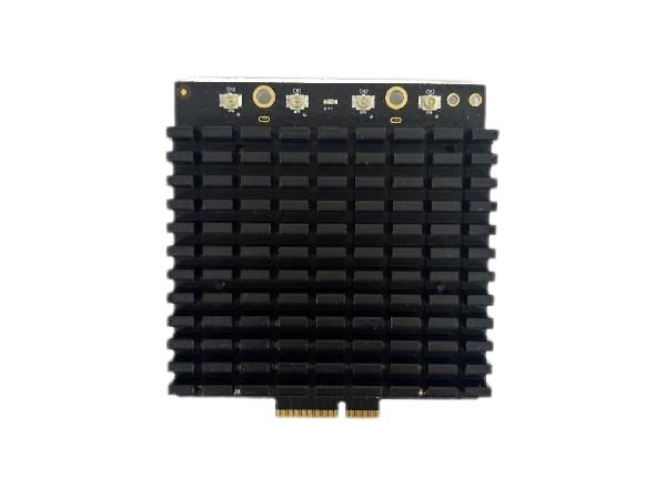
Module-level implementation: DR9274E-TB
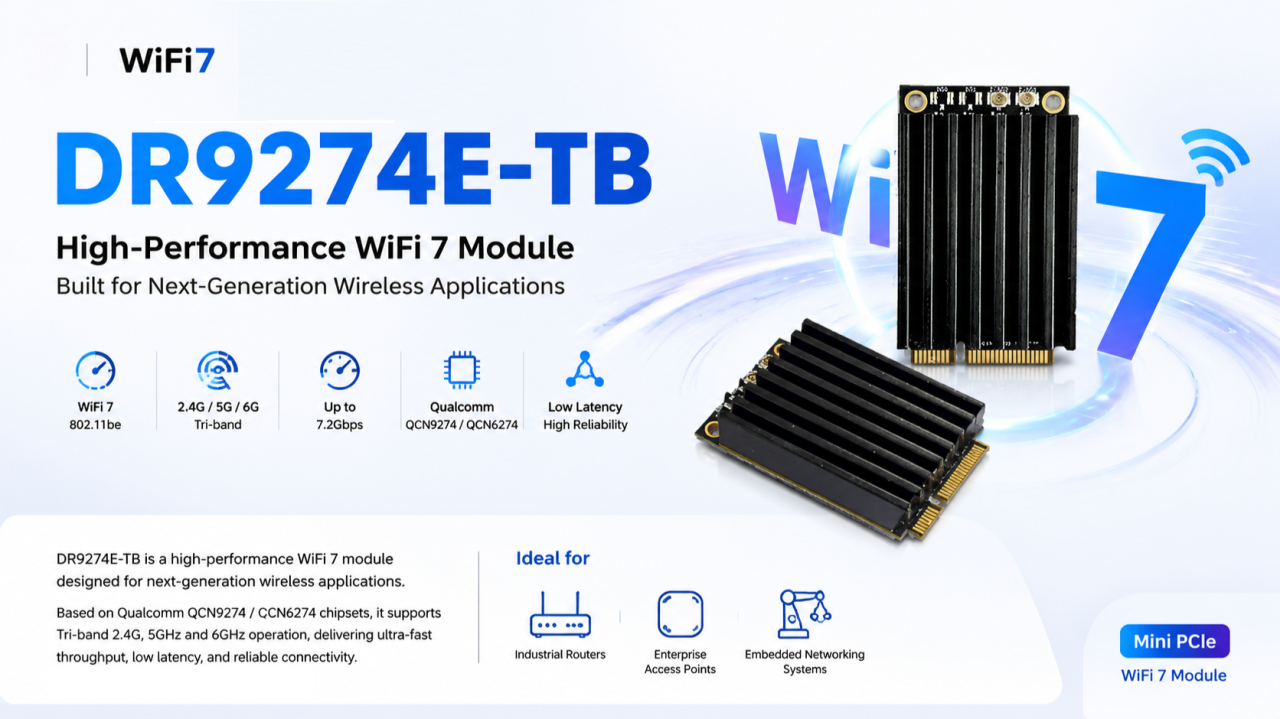
We built the DR9274E-TB around this exact requirement — a Mini PCIe WiFi 7 module for teams integrating wireless into embedded and industrial platforms rather than designing RF from scratch.
Specs:
Chipset: Qualcomm QCN9274 (5G/6G radio) + QCN6274 (2.4GHz radio) — Qualcomm’s WiFi 7 platform, not a rebadged WiFi 6E part
Band support: Tri-band, 2.4GHz / 5GHz / 6GHz
Antenna config: 2×2 MIMO
Interface: Mini PCIe — integrates without a carrier board redesign on most existing embedded platforms
OS support: Linux-compatible — relevant if your stack runs on JetPack, Yocto, or a custom embedded distro
Build: Industrial-grade components rated for continuous operation, not consumer-grade parts pushed into an industrial enclosure
Where the tri-band architecture actually matters
Not every application needs 6GHz. It matters specifically where you have:
High device density (multi-robot fleets, dense AP deployments)
Environments where 2.4/5GHz spectrum is already saturated by other systems
That covers most edge AI computing platforms, industrial routers/IoT gateways, enterprise APs in high-density environments, outdoor CPE/wireless bridges, and mesh networking nodes.
The engineering takeaway
Specifying wireless the way you did for a WiFi 5/6 design — pick a dual-band module, move on — leaves latency and reliability headroom on the table that your compute stack has already outgrown. Tri-band WiFi 7 with MLO isn’t a marketing checkbox; it’s a direct answer to the contention and jitter problems that show up specifically under production RF conditions, not lab conditions.
Happy to go deeper on channel planning, MLO configuration, or driver-level integration for teams currently specifying wireless for a Jetson-based or other edge AI carrier board.
📩 Reach out to 524WiFi for datasheets, samples, or OEM customization.
A recent PtMP deployment we worked on had a familiar problem: the hardware checked every box on paper — right frequency band, right range, right radio — but once more than a handful of remote stations came online, performance got uneven. Some stations ran fine. Others lagged, dropped packets under load, or just underperformed relative to what the spec sheet promised.
The instinct in situations like this is usually to blame the radio hardware. In our experience, the actual bottleneck is almost always the scheduling layer — how airtime gets allocated across stations, not the raw RF performance.
What we found
Standard TDMA firmware implementations often use static or near-static slot allocation — every remote station gets a roughly equal time slice, regardless of what that station actually needs or how far it is from the base station. That works fine at low station counts. It breaks down as deployments scale, because distance, interference, and per-station data demand aren’t equal across a real network — a fixed schedule fights the physical reality it’s trying to serve.
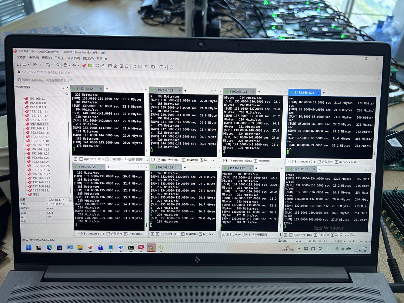
We rebuilt the scheduling logic on the firmware side to allocate airtime dynamically — closer to a priority/demand-weighted model than a fixed round-robin — and re-ran the same deployment topology: 8 remote stations, one base station, downlink test, same OpenWrt-based platform.
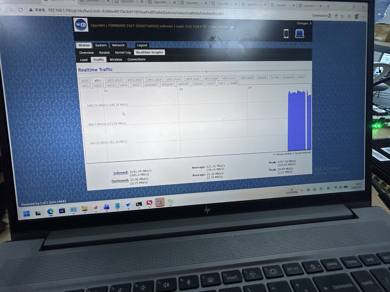
Result: per-station throughput of 130–265 Mbit/s, aggregate peak of 1,797.28 Mbit/s, aggregate average of 625.16 Mbit/s — with the spread between best- and worst-performing stations narrowing noticeably compared to the default static-scheduling baseline.
Why this matters beyond one deployment
The hardware didn’t change. The module, the antenna, the base station — none of it changed. What changed was the software layer managing how that hardware gets used across multiple simultaneous stations. That’s usually the part vendors don’t customize, because it means going deeper than swapping a chipset or bumping a spec sheet number.
This is also where we think there’s room for more collaboration than the industry typically does. A lot of teams building PtMP or multi-node wireless products — robotics, drones, distributed sensor networks — have strong hardware instincts but limited bandwidth to go deep on scheduling firmware, OpenWrt customization, or protocol-level tuning. That’s specifically the kind of work we do on the software side, independent of whether the hardware itself comes from us.
If your team has a multi-station deployment that’s hitting a similar wall — good radios, uneven real-world performance — we’re happy to compare notes, or scope what a scheduling-level fix would look like for your specific topology.
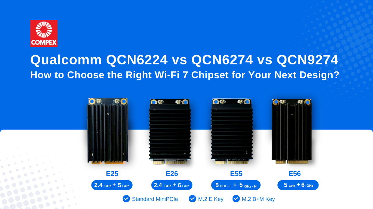
Wi-Fi 7 is rapidly becoming the standard for enterprise networking, industrial IoT, Edge AI and next-generation wireless infrastructure. When choosing between Qualcomm’s QCN6224, QCN6274, and QCN9274, engineering teams often ask us which one is “best.” The real question is: Which one fits your application’s capacity, thermal and cost?
Here is a quick breakdown to guide your next design:
Qualcomm QCN6224
It is designed for applications where cost efficiency and reliable Wi-Fi 7 performance are priorities, well suited for embedded systems and entry-level enterprise networking products. Supporting up to 128 concurrent clients, it offers reliable wireless performance for applications that do not require extremely high connection density. For many OEMs/ ODMs, QCN6224 offers an excellent balance between performance and affordability.
Qualcomm QCN6274
The Qualcomm QCN6274 targets enterprise-class networking. With support for the 6 GHz spectrum, wider channel bandwidth and up to 256 clients, it is well suited for enterprise access points, smart manufacturing, healthcare and campus networks where higher capacity is required.
Qualcomm QCN9274
The Qualcomm QCN9274 is Qualcomm’s flagship Wi-Fi 7 networking chipset for demanding enterprise and industrial applications. Supporting up to 512 concurrent clients, it is ideal for high-density enterprise deployments, mission-critical wireless infrastructure and industrial applications that demand maximum wireless capacity and low latency.
Maximum capacity, advanced RF performance, premium enterprise features
Rather than asking which chipset is “better,” a more important question is: Which chipset is the right fit for your application requirements?
Choose Qualcomm QCN6224 when cost efficiency and dependable Wi-Fi 7 performance are your priorities.
Choose Qualcomm QCN6274 when your product needs higher throughput, 6 GHz support and greater client capacity.
Choose Qualcomm QCN9274 when you are designing high-density wireless infrastructure where scalability, low latency and high concurrent client capacity are critical.
Looking Beyond the Chipset
Selecting the right chipset is only one part of developing a successful Wi-Fi 7 product. RF front-end design, thermal dissipation and host platform integration can add months to your development cycle.
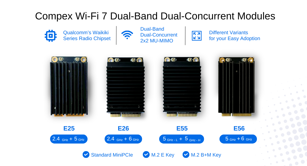
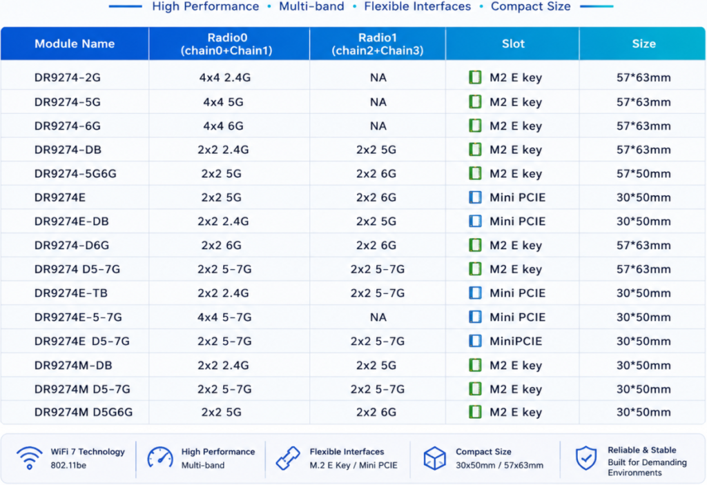
At 524WiFi and Compex, our Wi-Fi 7 Module Family supports single and dual-band configuration with both commercial grade and industrial grade chipset. Available in standard MiniPCIe form factor and M.2 variants, the module family are compatible with Qualcomm platforms as well as various third-party industrial CPU platforms, including Intel x86, NVIDIA and ARM-based processors such as NXP and Marvell, helping OEMs/ ODMs reduce integration risk and accelerate product development.
To learn more about Compex Wi-Fi 7 Standard MiniPCIe and M.2 Qualcomm-based Wi-Fi 7 module, contact us directly !
5One common assumption we encounter is that moving from 4G LTE to 5G will automatically improve network coverage. After all, newer technology should be better… right? The reality is a bit more complicated – again and again.
For many IoT applications, coverage is determined far more by frequency than by the generation of cellular technology itself. An LTE device operating on low-band can often outperform a 5G device using mid-band when it comes to indoor penetration and reach into challenging environments such as basements and utility cabinets.
Part of the early promise of 5G was that technologies such as Dynamic Spectrum Sharing (DSS) would allow operators to introduce 5G while leveraging the coverage footprint already established by LTE. While DSS certainly accelerated early deployments, many operators are now evolving their strategies as networks mature, balancing capacity, efficiency, and spectrum utilization to meet growing demand (https://www.lightreading.com/5g/the-quiet-sunset-of-5g-dynamic-spectrum-sharing).
Then there’s another point: 5G Standalone (SA) vs Non-Standalone (NSA). Most of today’s 5G deployments are still NSA, meaning they continue to rely on the existing LTE core network for signalling and control. True 5G SA deployments offer the full promise of 5G with network slicing and super low latency being key factors, but they remain relatively uncommon. Or, to put it another way: 5G Standalone deployments are quite (stand)alonely!
You also have the “LPWA is 5G” proponents but we’re talking real 5G here. So what’s the takeaway? The “best” cellular technology isn’t necessarily the newest one; the right choice depends on what you’re trying to achieve.
If your application requires high throughput, low latency, or is designed with future 5G capabilities in mind, then 5G may well be the obvious choice for you. On the other hand, if your priorities are coverage in difficult environments, low power consumption and/or cost control, LTE technologies still make a very compelling case. The good news? We really love this stuff.
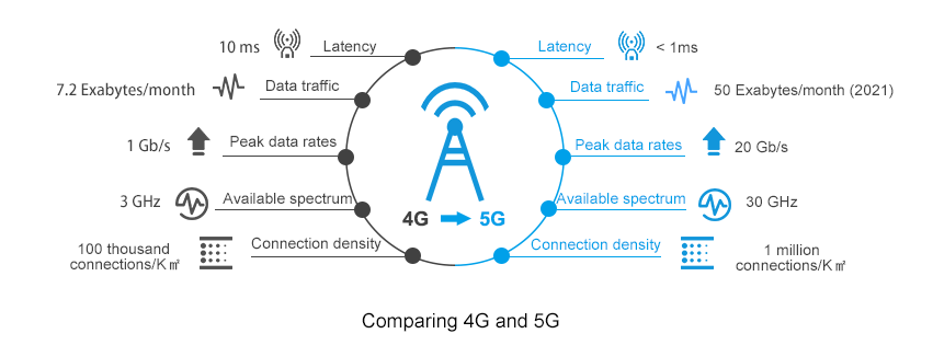
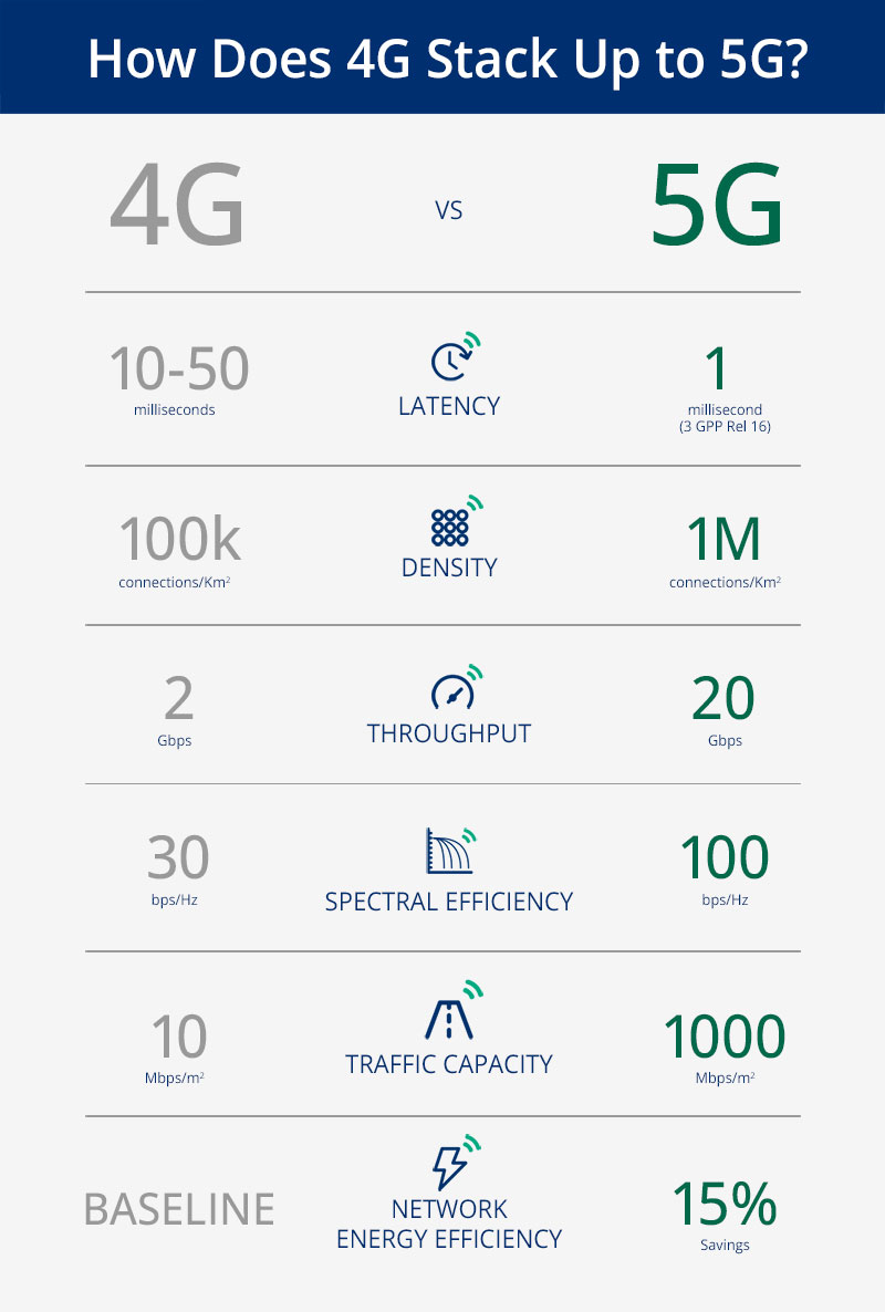
4G Vs. 5G Key Technology Differences
Choosing the right cellular technology isn’t always straightforward, but that’s where we can help. Whether you’re evaluating LPWA, LTE, or NR, we’d be happy to discuss your application, and help you navigate the intricacies of module selection to find the best fit for your project.
In this article, I will address and review the Key technology differences between 4G and 5G; reading this topic is crucial, especially if you have a good background in 4G and have just started your 5G Career.
This article will cover the differences between 4G & 5G for the following
Content
RAN Structure: 4G, 5G NSA & 5G SA
From the Radio Access Network side, The overall structure looks very similar, for example;
X2 interface connecting different 4G Nodes was replaced by the Xn interface
S1 interface connecting BTS Side to the Core network replaced by Ng interface
MME replaced by AMF and SGW replaced by UPF
From a superficial view, it is a matter of naming change; however, there are subtle changes implemented that leads to huge improvement; we will be addressing one of the points which can lead to improving latency in 5G SA.
RAN Structure
One of the main differences provided in 5G SA Architecture is that the User plane and Control function has separated; see below comments and the 4G & 5G Full Architecture for more details.
An important Characteristic of the 5G System is separating the user plane and control plane functions, which differs from the original 4G System architecture in the following:
In 4G: P-GW provides both control plane and user plane functions(IP Address allocation & Packet Forwarding)
In 5G: SMF Provides IP Allocation, and UPF provides packet forwarding
2. User and Control plane separation allows independent scaling of the two functions
Operators can add more user plane capabilities without having to add more control plane
Minimize latency by distributing User plane and keeping it geographically close to the AN
Packet Gateway provides both User plane and Control Plane function in 4G
4G Architecture
While in 5G, Only UPF provides User plane function.
5G Architecture: Pictures captured from 5G NR in Bullets
Quality of Service: 4G & 5G
For the QoS Part, there is an essential change in the way of how the QoS is being allocated.
In 4G, EPS Bearer is responsible for providing E2E User Plane connectivity between the UE and Access Point Name “APN” within the Packet Gateway
*APN defines the interface to the external data network
The point here is that EPS Bearer has a one-to-one mapping to the QoS, This means that the User needs to establish a new EPS bearer every time there is a new QCI assignment, Only One QoS(Example QCI 9 can be assigned to one DRB) with no flexibility.
4G QoS
In 5G, PDU Sessions is responsible for providing E2E User Plane connectivity between the UE and Data Network Name “DNN” within the User Plane Function ( UPF)
*DNN defines the interface to the external data network
However, Unlike 4G EPS Bearer, PDU Session supports one or more QoS Flows, Which means that QoS Flow to radio bearer mapping is not necessarily one-to-one mapping and multiple QoS can be mapped to the same Radio Bearer.
5G QoS
Note: QoS Flows belonging to different PDU Sessions are mapped onto different DRBs.
Radio Protocol Stack: 4G & 5G
SDAP Primary Task:
Service Data Application Protocol (SDAP) is responsible for mapping QoS bearers to radio bearers according to their quality-of-service requirements. This protocol layer is not present in LTE but introduced in NR when connecting to the 5G core network due to the new quality-of-service handling
The new SDAP (Service Data Adaptation Protocol) primary function maps each QoS Flow onto a specific Data Radio Bearer
•Multiple QoS Flows can be mapped onto a single DRB or,
•Single QoS Flow can be mapped onto a single DRB.
Radio Protocol Stack: SDAP Layer added in User-PlaneSDAP Layer
Overall Technology Comparison
4G Vs. 5G Bandwidth
4G Supports a maximum up to 20Mhz BW, While 5G is up to 400Mhz
5G offers less Guard Band(2~5) and Higher Spectrum Utilization(Utilizing up to 95% of the Channel BW, While 4G Utilize 90%)
Up to 20x Higher Bandwidth and New Spectrum Definition. (ex. mmwave)
NR Offers Less Guard-band and Higher spectrum utilization
*Source: 3GPP TS 38.101 & TS38.104
Frame Structure Comparison: 4G & 5G
The following summarized the main differences between 4G & 5G Frame Structure
Frame and Subframe duration remained the Same for 5G
Number of Symbols in a slot is now fixed to 14 in 5G (4G is fixed to 7)
5G has a flexible numerology, which allows different configurations as the Slot Duration relies on SCS(Sduration = 1 /SCS)
5G is now using a Slot as a scheduling Unit instead of Sub-frame compared to 4G
NR RB Resource Grid is double 4G(14 vs. 7 OFDM symbols in one RB )
Physical Channel & Signals Comparison : 4G & 5G
The below table summarizes the main differences in Physical Channel and Signals
Downlink Comparison: Physical Downlink Control Channel(PDCCH)
In LTE, PDCCH control channels are always distributed across the entire system bandwidth.
NR PDCCHs are designed to transmit in a configurable control resource set (Called CORESET).
Uplink Comparison: Physical Uplink Control Channel(PUCCH)
In 4G, PUCCH is transmitted in one or more Physical Resource Blocks (PRB) at the edges of the system bandwidth and is only supporting Long-Format(duration 1 ms)
While 5G supports both Long and short format, Where short format provides the following:
1~2 Symbols over the complete
Provides Better Latency
PBCH & Synchronization Signals: 4G & 5G
There are 2 main changes in PBCH and SS compared to 4G:
PBCH and SS are now being combined into SSB
SSB Frequency domain location is flexible and can be configured at different locations based on the network requirements(4G PBCH & SS are fixed at the center of Channel BW)
Broadcast Channel Comparison: 4G & 5G
4G Provide Wide Beam coverage, while 5G provides narrow beam coverage for broadcast channels, which can improve the Coverage and Quality
Reference Signal Overhead comparison: 4G & 5G
5G Overhead is almost half 4G, and the mean reason behind that 5G has no Cell Specific Reference Signal as 4G
As you know that CRS was all the time transmitted “Always on” over the entire BW and consume a large number of resource elements within the Resource block
While 5G uses DMRS for channel demodulation instead of CRS.
PDSCH DMRS offers much less overhead compared to CRS due to the following:
DMRS is transmitted within the set of RBs allocated to PDSCH. i.e, if a UE is allocated 10RBs for PDSCH, then both PDSCH and DMRS will be transmitted across those BW
DMRS Configuration type 1 uses 6 RS within one or two symbols, which add around 3.6% up to 7% overhead to 5G, while 4G offers from 9% to 17% overhead. Please see the below picture for more details and refer to the below-attached video for more information.
Key differences in Link Budgets: 4G & 5G
4G & 5G almost have the same Link Budget Basic Methodology
Link Budget is counting all of the gains and losses from the TX through the medium(Free Space, Cables, etc.) to the receiver
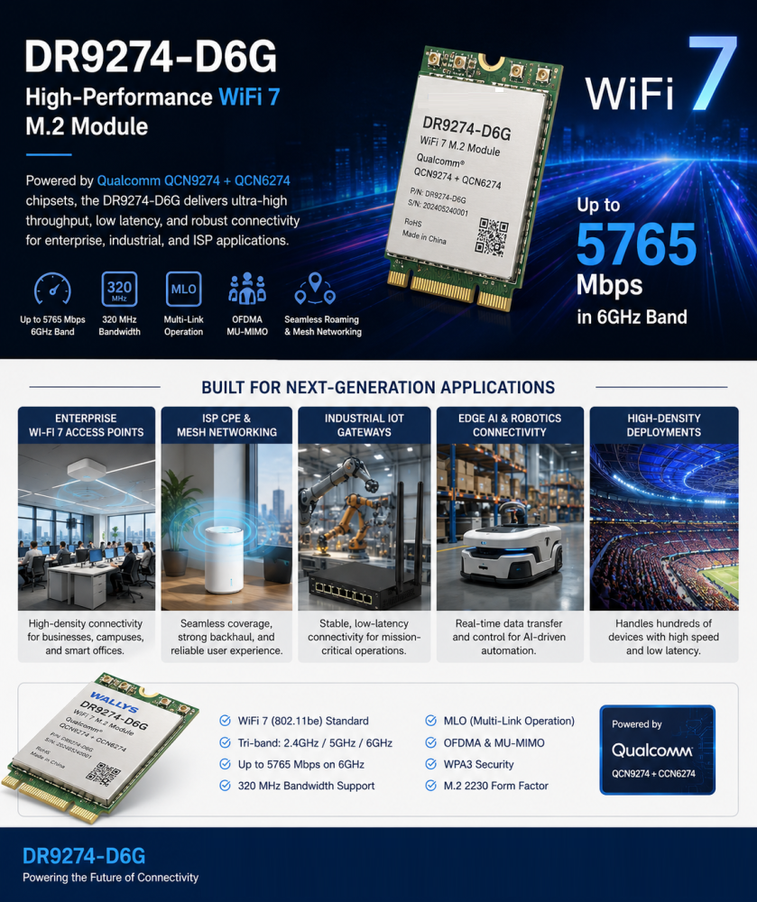
Powered by Qualcomm QCN9274 and QCN6274 platforms, the DR9274E WiFi 7 module is designed for applications requiring higher bandwidth, advanced connectivity, and future-ready wireless performance.
Potential applications include:
AI vision drones
Autonomous aerial robots
Industrial inspection UAVs
High-resolution video transmission systems
With WiFi 7 capabilities, it provides a powerful wireless foundation for intelligent devices requiring faster data exchange and more reliable connections.
DR9074 WiFi 6E Module: Reliable Connectivity for Industrial UAV Applications
Based on Qualcomm QCN9024, the DR9074 supports Tri-Band WiFi 6E operation across 2.4GHz, 5GHz, and 6GHz.
It is designed for applications requiring:
Stable wireless links
High-performance data transmission
Flexible frequency selection
Industrial deployment reliability
Suitable for:
Inspection drones
Mapping systems
Smart agriculture UAVs
Edge AI devices
Connecting the Future of Autonomous Flight
The future of drones will not only depend on better AI algorithms.
It will depend on the complete technology ecosystem:
AI provides intelligence. Sensors provide perception. Wireless connectivity enables action.
A smarter drone still needs a stronger wireless link.
At 524WiFi and Wallys, we are committed to providing Qualcomm-based WiFi 6 and WiFi 7 platforms for the next generation of drones, robotics, and edge AI applications.
The future of autonomous flight will not only be smarter.
Let us share our experience with Qualcomm Atheros WCN6856 based Wi-Fi 6 Triband modules from Sparklan. These WiFi6 modules are very popular. Many professional customers are requesting testing samples and want to use them for their projects.
Open Source Linux ath11k driver is available, works but has limitations.
If the customer needs DBS, they will need to apply the ath11k patch. However, after applying the patch, DFS will not be available, and many functions will not work with ath11k. In many cases, we have already suggested using the official QCA driver. Unfortunately original QCA driver is for older Linux kernel only – WNFQ-269AX(BT) Qualcomm official driver supports Linux Kernel version 5.4 & 5.10 & 5.15.
“For DFS and support for more client connections (+60) , they will need to use the official QCA driver.”
Sparklan can provide the original driver but every customer has to sign the NDA . If you are interested in , then please contact us and provide your project description and company details. We will send the NDA for you.
Please follow the steps higher to replace the firmware BDF.
Here is an older success story from our customer, maybe thsi can help to many other to develop relaibel working x86 Linux based device with WCN6856 based Wi-Fi 6 Triband modules :
I think we will have to stick with the open source ath11k driver for now since we already are committed to 6.1.x.
I have since migrated this project to Debian 12, also on 6.1.x. I can confirm the exact kernel version. However I was able to install ath11k on Debian 12 core (no X since this will run headless) along with the open source firmware and I do have hostapd working now. I am yet to activate dnsmasq, a bridge that includes the lan interface, etc. So far it seems that what I am stuck on is 2.4GHz + 5GHz DBDC. I’ve experimented with hostapd.conf quite a bit and I cannot seem to figure out how to do this. Typically with DBDC I have seen two wifi interfaces enumerate in linux. I only see one (named wlp1s0) in my case. Performing sudo iw list does show all of the correct frequencies in the supported list (including 6GHz which is not necessary for my application).
Strangely, after a reboot, the only way that I can correctly set the regulatory region (sudo iw reg set US in my case here) is after I perform a manual sudo iwlist scan. This could be an issue because I will want the appliance to reboot with hostapd activated automatically (presumably by systemd?)
I would be happy to share my hostapd.conf and anything else from my configurations to get this working. I feel that I am quite close to success and with just a few more configuration file adjustments plus the correct systemd service definition this project will be complete.
The hostapd.conf and dnsmasq.conf are attached. These are working well except:
No SDBC. I don’t seem to see in a scan anything except the 5GHz radio.
Trying after boot:
armbian@nanopi-r5c:/$ sudo hostapd /etc/hostapd.conf wlp1s0: interface state UNINITIALIZED->COUNTRY_UPDATE Frequency 5180 (primary) not allowed for AP mode, flags: 0x100853 NO-IR Primary frequency not allowed wlp1s0: IEEE 802.11 Configured channel (36) or frequency (5180) (secondary_channel=1) not found from the channel list of the current mode (2) IEEE 802.11a wlp1s0: IEEE 802.11 Hardware does not support configured channel Could not select hw_mode and channel. (-3) wlp1s0: interface state COUNTRY_UPDATE->DISABLED wlp1s0: AP-DISABLED wlp1s0: interface state DISABLED->DISABLED wlp1s0: AP-DISABLED wlp1s0: CTRL-EVENT-TERMINATING hostapd_free_hapd_data: Interface wlp1s0 wasn’t started nl80211: deinit ifname=wlp1s0 disabled_11b_rates=0
Produces hostapd failure every time. However if I instead first:
armbian@nanopi-r5c:/$ sudo ip link set wlp1s0 up armbian@nanopi-r5c:/$ sudo iwlist scan armbian@nanopi-r5c:/$ sudo iw reg set US armbian@nanopi-r5c:/$ sudo hostapd /etc/hostapd.conf wlp1s0: interface state UNINITIALIZED->COUNTRY_UPDATE wlp1s0: interface state COUNTRY_UPDATE->HT_SCAN wlp1s0: interface state HT_SCAN->ENABLED wlp1s0: AP-ENABLED
Doing these steps produces a perfectly running ap bridged with one of the two ethernet NICs and with a working DHCP server. It seems stuck in 5GHz and at lower speed classes. But otherwise it’s working. These extra steps are quite tricky to run without a bunch of shell scripts called by systemd which is not as reliable as I would prefer.
sudo iw reg set US
Does nothing unless I first: sudo iwlist scan
NetworkManager (NM) is disabled and I am using systemd-networkd. This is a headless micro-server and NM just got in the way of everything.
I feel like I am very close to having this working perfectly!
More system information follows. Thanks.
armbian@nanopi-r5c:/$ uname -a Linux nanopi-r5c 6.6.31-current-rockchip64 #1 SMP PREEMPT Fri May 17 10:02:40 UTC 2024 aarch64 GNU/Linux
4. iw list —> Check 5G Frequencies “NO-IR” disappears
However, I must remind you again that they will need to apply the ath11k patch for DBS.
Result – Super helpful and I can report I have success, I have an AP, I have rather good performance for a software AP, and I’m going to send this to testing.
In case anyone else was wondering: on current Debian the wifi needed a new file /usr/lib/firmware/ath11k/WCN6855/hw2.0/board-2.bin which was extracted from either Debian unstable or https://git.kernel .org/pub/scm/linux/kernel/git/firmware/linux-firmware.git/
When people talk about autonomous robots, the conversation usually focuses on AI models, sensors, cameras, and navigation algorithms.
But there is another critical layer that often determines whether a robot system succeeds in real-world deployment:
Wireless connectivity.
A robot can have advanced AI capabilities, but without reliable communication, even the smartest robot may struggle in a dynamic industrial environment.
For large-scale robot fleets, connectivity is no longer just a networking feature. It becomes part of the robot’s operational reliability.
The Reality of Wireless Challenges in Robot Deployments
In warehouses, factories, farms, and outdoor industrial environments, robots are constantly moving.
An AMR (Autonomous Mobile Robot), for example, may need to:
Move across different areas with changing RF conditions
Maintain real-time communication with control systems
Upload high-resolution camera data
Receive navigation and task instructions
Coordinate with other robots in the same environment
During these operations, wireless networks face several challenges:
1. Roaming: Staying Connected While Moving
A robot moving through a large facility often needs to transition between multiple access points.
A poor roaming experience can cause:
Packet loss
Video interruption
Control delays
Temporary disconnection
For industrial robots, even a short communication interruption can affect efficiency and safety.
Advanced roaming mechanisms such as 802.11k/v/r help devices make faster and smarter roaming decisions by improving network awareness and reducing handover time.
However, successful roaming also depends on:
Proper RF planning
AP deployment strategy
Client behavior optimization
Network management
2. Latency: Every Millisecond Matters
Many industrial robot applications require real-time communication.
Examples include:
Remote monitoring
Vision-based inspection
Autonomous navigation
Robot fleet coordination
High latency can impact:
Motion control
Response time
Task execution efficiency
The challenge is not only achieving high throughput.
A network can provide high speed but still suffer from unstable latency due to:
Network congestion
Interference
Poor link quality
Inefficient routing
Reliable industrial wireless networks need predictable performance, not just peak speed.
3. Wireless Stability in Complex Environments
Industrial environments are very different from homes or offices.
Factories and outdoor deployments may include:
Metal structures causing reflections
Moving equipment blocking signals
Multiple wireless networks creating interference
Large numbers of connected devices
A robot fleet may experience changing wireless conditions every moment.
This requires networks that can adapt dynamically.
Important capabilities include:
Intelligent channel management
Interference detection
Dynamic path optimization
Mesh networking
Traffic prioritization
Why Traditional Wi-Fi Approaches Are Not Always Enough
A standard Wi-Fi deployment may work well for static users.
However, robot fleets introduce new requirements:
Mobility
High device density
Continuous connectivity
Low latency
Reliable uplink performance
The network needs to be designed around the robots’ movement and operational workflow.
Building the Wireless Foundation for Next-Generation Robots
The future of autonomous systems will depend on the combination of:
AI + Robotics + Reliable Connectivity
Advanced wireless technologies such as Wi-Fi 6 and Wi-Fi 7 bring important improvements:
Higher capacity
Better multi-device performance
Lower latency
Multi-band operation with MLO
Improved reliability in demanding environments
But technology alone is not enough.
Successful industrial deployments require:
The right wireless architecture
Proper RF optimization
Reliable hardware platforms
Long-term firmware support
Real-world validation
Final Thoughts
Autonomous robots are becoming smarter every day.
But intelligence alone does not guarantee successful deployment.
Behind every reliable robot fleet is a reliable communication infrastructure.
The next generation of industrial automation will not only depend on better AI algorithms — it will depend on wireless networks that can keep robots connected, responsive, and operational in the real world.
Reliable connectivity is the foundation that allows autonomous robots to truly become autonomous.